Rubber Suspension Bushings (and Revisiting Bushing Preload)

Featured

This isn’t the first time we bring this up to you, our customer. Actually, it is a very common problem for people setting up their suspension. Once our suspension is installed, they lower the car back to the ground and notice uneven ride height from left to right side.

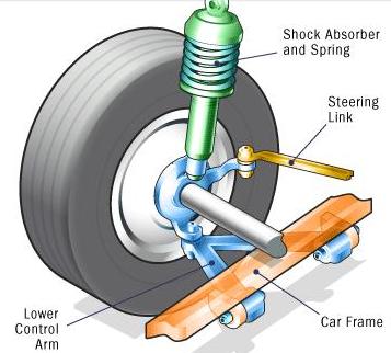
We’ve found this to be an issue with a few vehicles, mainly vehicles with a multi-link or “double-wishbone” suspension. And mainly this is because these types of suspensions have more rubber bushings in their suspension arms.

Once you disassemble some suspension arms in order to access the shock absorber assembly, like in a Mazda RX-8 for example, you’ll have to reassemble the arms through their respective nuts/bolts. That’s not uncommon, and this probably sounds relatively straightforward to you.

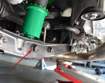
However, what we fail to account for is the fact that we typically do this when the vehicle is in the air, on jackstands or on a lift, leaving the suspension drooping down (fully extended).

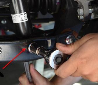
Why is this important to note? Well, once you start to loosen these nuts/bolts at suspension arm joints, you’re essentially removing any tension on the bushings associated with each arm. When that same bushing needs to be reinstalled (by way of connecting the arms with the nuts/bolts you removed), you end up tightening all these bushings while the suspension is drooping down (fully extended). Those bushings that were just recently relieved of the tension they were once under are now at zero preload. Now, when you put the suspension back on and the vehicle back on the ground, these zero preloaded bushings start to twist. The only issue is the twist isn’t necessarily going to be even from any specific corner. This leads to the uneven ride height you might be experiencing.

How can we prevent this uneven ride height? Well, this requires loading up the suspension PRIOR to tightening any nuts/bolts to these suspension arms. Obviously this isn’t easy to do since the best way to load the suspension is to put the car back on the ground. There are 4-post lifts that also serve as ramps. This gives you undercar access to these nuts/bolts that you can tighten. Those with vehicle ramps tall enough to let you creep under the car to tighten any nuts/bolts is also good. However, this is the BEST way to avoid any bushing preload issue. We must note, though, that this doesn’t cure uneven ride height completely, since all vehicles do have a weight bias from one side to the other, and of course from front to back.

Does this mean that rubber bushings are a terrible design? No, not at all. In fact pretty much all production vehicles use rubber bushings. They’re effective in terms of performance and cost, which most OEM companies are very sensitive about. Quite honestly, they’re probably more durable that some aftermarket floating bushing designs since they really don’t require maintenance (periodic greasing), with the exception of sway bar bushings. Once they’re bad, you have to either replace the bushing or replace the arm that the bushing is pressed into (the latter being the most commonly offered for ease of installation).

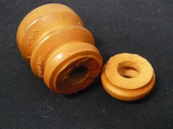
Again, the difference between rubber bushings compared to typical aftermarket floating bushings is that the rubber bushings have any steel components, such as the crush tube and shell, bonded together through the rubber filling. Floating bushings, typically polyurethane in the aftermarket, simply have the bushing free moving between the shell and crush tube. This is great for having free-pivoting arms, allowing the damper and spring to do their job more effectively, but also requires quite a bit of maintenance to make sure they’re greased properly (you don’t want polyurethane to dry up). Not a big deal if you really enjoy wrenching on your car, and in some cases, aftermarket bushing manufacturers have included zerk fittings to either the steel tube or crush tube to ease the greasing process! Not all bushings have easy access for a zerk fitting to be placed, however, which has led to the development of bolts being gun drilled and cross-drilled and a zerk fitting threaded to the end.

Rubber bushings, again bonded to any steel shell or tube, don’t allow this free pivoting. Instead, the bushing relies on strain, or stretching of the rubber, meaning you have a limited range of motion either up or down, or even side to side. For most cars, this isn’t a problem.

Because most rubber bushings are “maintenance-free”, over long periods of time, they will dry rot and the rubber material will break away. This creates excessive movement of the suspension arms (moving in directions not intended), and can cause poor and unsafe driveability.

Bump Stop Trimming

Without a doubt lowering springs is easily one of our biggest sellers. It’s a simple upgrade for someone wanting to lower their vehicle but not wanting to really sacrifice much in the way of ride quality, and it’s also much more affordable than a coilover kit. This is an especially common upgrade for people with newer vehicles, or cars still under warranty (or maybe they don’t have much to spend since they just got a new car).

As many of you may know, we make our lowering springs compatible with factory (OEM) dampers. Not necessarily in just fitment, but also in spring rate. Our lowering springs are not very aggressive. If you take a look at our lowering springs’ specifications for your vehicle, you may see that the ride height drop is not too aggressive (maybe better than some other manufacturers). Some other applications of our lowering springs may seem to be very aggressive. It’s all a matter of how much room we have to play with when designing our lowering springs.

Most important for customers is reducing the tire to fender gap. As of the past few years, the request is for a “flush” fitment, where the tire just closes up the gap with the top of the fender opening. As much as possible, we want to create that type of fitment for the customers, even making a staggered ride height drop for front and rear to achieve a nice and even wheel gap. But, where we reach limitations is the factory damper stroke length.

Some factory suspensions have very limited stroke length, and this makes it increasingly difficult to design a spring that will aggressively lower a vehicle. That isn’t the only limitation. We look at clearance with the fender, within the wheel well, as well as how it may affect steering/suspension geometry. We always design our lowering springs to give you the most ride height drop in as safe a level as possible.

So, in regards to trimming bump stops- why is this important? If we find that aspects, other than damper stroke length, seem to be very generous, we know that we can make a lowering spring that will work with a shortened bump stop. So we include a chart by vehicle application that shows how much you will need to trim for front and rear when installing our lowering springs.

Some cases may require a different type of trimming style for the bump stop. Typically it is just trimming the bottom portion of bump stop and retaining the top piece (A Type). Sometimes it’s the reverse (B Type). In other cases, you may need to trim a middle section and retain the top and bottom piece (C or D Type). See below the different style cuts we recommend, depending on the vehicle:


bump stop trim style

We know several customers skip the bump stop trimming step. This can cause several issues. We’ve added this measure so that you can retain a bit more stroke length at the newly lowered ride height. This also helps improve ride quality. Because the bump stop is made of a high durometer polyurethane material, it is like a secondary spring, but a really stiff secondary spring. Since the dampers are not valved to handle such a stiff secondary spring, it can make rebound feel really harsh. Some may say bouncy. Constantly hitting the bump stop can cause the damper to prematurely wear or potentially blow out, too.

bump stop trim 001

Bump Stops come in all sorts of goofy shapes. Mind you, these were engineered with a specific design.

bump stop trim 003

The bump stop itself is a really lightweight piece, but it is of a high durometer and takes a lot of force to compress. At least it is easy to cut into.

Fortunately, you can cut easily into the bump stop using a box cutter/safety blade. It slices pretty easily.

bump stop trim 004

Here’s a picture of a 2015 Camry bump stop. This is a more typical design that we see- top is a larger outside diameter and tapers, with billows that make it easier to determine which section we recommend trimming.

bump stop trim 005

Using a safety blade, we’re able to cut a bottom portion of the Camry’s bump stop. We’ll be retaining the larger piece on the left and reinstalling onto the front strut.

bump stop trim 006

This bump stop uses some plastic ring, likely to control the bump stop’s compression. In our case, we need to trim a middle section.

bump stop trim 007

We cut this into three pieces, and the middle piece will be removed. The remaining top (left) and bottom piece (right) will be reassembled on to the damper.

So, while you will have your suspension taken a part for a little while when installing our springs, take the time to see if your bump stops will need to be trimmed. Check the included instructions with our lowering springs to find out that info.

Applying Suspension Preload

What’s up, people? Here I go again with some helpful tips when installing lowering springs and coilover kits.

I have to honestly say that we hear the following questions countless times during the work week.

“Why is one corner of my car higher than the other?” Or, “Why is my ride height uneven?”……………..(AHHH..here we go again)..lol.

The solution is actually quite simple. The first things to check are for worn-out suspension components. We advise to check all components carefully and thoroughly. Anything can contribute to the issue previously mentioned. Worn out bushing, incorrect spring, blown damper, spring perches are not even, missing or mis-installed components, etc. If everything checks out fine, then the only candidate that would contribute to uneven ride height would be suspension pre-load. This issue is commonly encountered when installing lowering springs and/or dampers on vehicles with double wishbone or multi-link suspensions.

In some cases the lowering spring or coilover kit is installed while the suspension is in a full droop.  This means that the bolts on the lower control arm were tightened while the arm was hanging down. In other words, there is no load on the suspension when tightening all components.  When the vehicle is brought back down the bushings twist causing the suspension to not settle correctly thus resulting in a uneven ride height.

The first thing you want to do is lift the car back up. Them loosen the bolts on the control arm and shock absorber. Once in the air use a second jack to apply load on the control arm. This simulates as if the car was on the ground and the control arm is back to its original position. Then re- tighten all the bolts loosen in the previous step. Follow this process with all four corners, then bring the vehicle back down. If you follow these instructions, this should help get the vehicle to the correct ride height. Plus,
you will have learned another method on how to correct uneven ride heights, if you ever run into a similar situation in the future!


Coilover Spring Swap

I have not really touched my EVO since my last track day back in May. The car felt the same, stable. Maybe too stable, meaning a tendency to understeer. I tried to compensate by aggressive trail braking and almost jerking the wheel to get weight transfer but the wide tires, wide body and aggressive aero keep the car super planted.

I have been meaning to try some different spring rates or R-comp tires for, hmmm… about the last 2 years. Spring rates and tires are VERY related. Higher grip tire = higher spring rates and vice versa. I am currently using 14kg front and 12kg rear springs plus slightly larger sway bars for front and rear. Over the past couple of years I have run Hankook RS2, Azenis RT-615 (non K), Continental CSC3 and Continental ExtremeContact DW. All street tires with similar performance. In my mind I thought my next purchase would always be a set of R-Compounds or extreme performance summer tire like an Advan Neova. But I just never seem to get there. I always end up buying something else, like my Voltex street front bumper, HKS V-Pro (which is sitting on a shelf in the garage), new DEFI Advance ZD, etc….

It FINALLY dawned on me that I should stop being lazy and just switch the springs to better suit the tires I always seem to use. A cheaper and more practice solution than spending $1300+ on tires. So last night I bought some softer springs (MSRP $120 per pair) and installed them. I went for a 2kg spring rate change. Now I have 12kg front and 10kg rear. The spring swap went relatively quickly. Depending on the damper we recommend a damper revalve if the spring rate is changed by +/- 2kg (for BASIC and Street Basis +/- 1kg since the damper is not damping force adjustable).

New 10kg springs for the rear. The 12kg originally on the rear will go to the front of the car since my setup uses SQ type springs for front and rear.

Here is a little useful information: This is how you can check what TEIN springs you have. The number printed on the spring is the individual spring part number. The part number listed on our website, catalog, etc…is a kit part number. So these springs are from kit part number SQ100-01175. The “SQ” designates a type of spring which is in this case is a standard straight spring, 65mm ID, 175mm free length.  The “100” after SQ is for the spring rate, 10kg. ex. 050 = 5kg. 140 = 14kg. “01175” is for the free length. Just pay attention to the last three digits which is the length. ex. 01200 = 200mm. 01150 = 150mm.

On the actual spring the part number is “Q100-GOC”. “Q” represents spring type, 65mm ID, 175mm free length. “100” is spring rate = 10kg. “QOC” is the LOT/ batch in which this spring was made.

First, I measured wheel center to fender height before starting. Maintaining the ride height will mean I will not need to do an alignment.

Not using the lift for this. (Getting lowered cars with aero parts on a normal lift is a pain. Got to drive up on ramps, use wood, adjust the risers on the arms, etc…) Simple jack and stands is quicker for something like this.

Started with the rear since my rear springs will go onto the front of my car. Super easy since my interior trunk panels are not installed.

I use Simple Green and a rag to clean off the coilovers. Then I inspect all components of the coilovers for damage, etc… I made a small adjustment in spring seat height to maintain ride height with the new softer spring rate. If the spring seat or damper length is not adjusted, the ride height will be lower due to the softer spring rate (softer spring will compress more = lower ride height).

Now for the front. Cool trick on the front of the EVO 8/9 and maybe older gens is that the front spring can be swapped without removing the damper. This means the alignment is not affected since you never even loosen the upright (hub bracket) bolts. Plus this saves LOTS of time.

Just remove the top nut then top mount. Then the spring can be removed and swapped through the strut tower. Depending on what type of tower bar you have, the bar may need to come off. My aluminum Carbing 3-pt. bar does not need to be removed as it has an open top design (quick spring change compatible and EDFC compatible).

Removed my EDFC motor first. Then I slowly removed the top nut with a 21mm deep socket. (Impact Guns need to be used with care as internal damper damage may occur if used excessively).

Used my leg to push the hub down and got the piston shaft out of the top mount. I just angled the damper in the fender well so it was out of the way while I removed the upper mount.

After removing the EDFC strut kit parts and upper spring seat the main spring comes right out.

After swapping the spring I re-installed the top mount then used a floor jack to lift the damper back up into the top mount. Jack was placed under the under arm and I slowly raised it up.  Re-tightened everything and re-installed the EDFC motor. Lastly I adjusted my shell case length by a few mm to maintain the original ride height.

I use a paint pen to mark the seat locks so I will know if they get loose. Be sure to torque the lower bracket lock.

Car back on the ground. I moved the car around to settle everything. Lastly I re-measured the wheel center to fender to ensure my ride height/ alignment has not changed.

All done. Now it is time for a test drive and a little fun. Hope to be testing the new spring rates next month at ButtonWillow Raceway.

Lowering Spring Installation Tips

Many people assume that our S. Tech and High.Tech lowering springs do not need any special attention when being installed but that is incorrect.

Here are some tips to ensure your vehicle reaches the intended ride height and driving characteristics.

Note: we test fit and test drive all applications on OEM vehicles. So if your vehicle has an added turbo kit, audio system, heavy body kit, motor swap, basically anything that significantly adds or reduces weight you may not achieve the same results as from our testing.

Bump Rubber – needs to be modified as shown in our instructions. If the bump rubber is not modified as needed the ride height may not reach advertised drop and ride quality may be deminished due to lack of shock absorber stroke.

The OE bump rubbers may need to be trimmed to allow maximum stroke of the shock absorber in conjunction with the S.Tech or High.Tech lowering springs.

Spring Placement – placement needs to be the same as OEM. Front springs have a “F” in the beginning of the part number while rear springs have “R”. The part number should also be right side up. If the springs are not mounted correctly within the shock absorber perch or on the wrong side/ wrong shock  ride height/ performance/ comfort can be greatly affected.  Also check the OE rubber spring seats to insure they are positioned correctly as they shift during installation causing the ride height to be off. Certain applications do not require the use of OE rubber spring seats or rubber insulator on the lowering spring if the TEIN Silencer Rubber is included on the areas which would sit on the lower or upper spring seats.

The photo illustrates a High-Tech spring lined up correctly with the OE shock absorber.

Aftermarket Replacement Shock Absorbers – can be different in design causing the ride height to be higher or lower than advertised. Always use OE, or OE replacement shock absorbers to avoid any ride height or fitment issues. TEIN lowering springs are designed and developed to be used with OE shocks/struts.

Suspension Preload – During installation the suspension components should be tightened when the suspension has load. If not done correctly the ride height may be affected. This is especially important on multi-link suspension setups. Rubber or Poly bushings located in the suspension arms should be tightened when the arm is at its normal position which is when the car is on the ground. A lot of people tighten the suspension while at full droop (when the car is off the ground and suspension is hanging). Once the vehicle is placed back on the ground, the bushings twist and can cause a difference in ride height.

In this picture the car is off the ground and the suspension is preloaded by the floor jack. This sets all the rear left suspension components to their normal position and then all bolts are tightened.

We recommend a TEIN Authorized Dealer for installation and an alignment about a week after installation. You can find a complete list of TEIN Authorized Dealer HERE.

EDFC Motor Install Part 2

Here is part two of how to properly install EDFC motors (strut type, inverted shown). For this type of install is not as common as the last, but requires additional steps being that the motor is more exposed outside of the vehicle.

Additional tools you will need for this install is;

Small flat head screwdriver

1.5mm Allen wrench

Silicone sealant

For this install, it is recommended to do it with the damper off the vehicle and to remove the lower bracket for more clearance.

1st step: With a 1.5 mm Allen wrench, remove the click knob. Then you will need to use the 8mm click wrench to remove the click assembly. Once removed use the 3mm hex wrench to remove the original hex bolt from the damper.

Parts removed; original hex bolt, click assembly, click knob. Along with tools used in removal process.

2nd Step: Add a small amount of supplied grease (orange bag) to the EDFC hex bolt threads and install the EDFC hex bolt until flush with the top of the piston rod. Be sure not to add threadlocker (red tube) to this part!

EDFC hex bolt installed with grease and flush with top of piston rod.

3rd Step: Add the supplied threadlocker (red tube) to the outside threads of the top of the piston rod. Please note, not a lot of threadlocker is needed nor does it need to cover all the threads.

Area shown of where to apply the threadlocker to piston rod.

4th Step: Install the EDFC motor to the piston rod. This is the most important part and is sometimes easier with some help. What you need to do is place the EDFC motor shaft into the EDFC hex bolt. Now turn the EDFC motor 3 full rotations. At this point the EDFC motor should have started to thread onto the piston rod. Next, with your small flat head screwdriver, turn the top shaft of the EDFC motor 2 full turns clockwise (shown below). Continue to switch between turning the EDFC motor and top shaft in 3 or 2 specified full turn increments until the EDFC motor cannot turn anymore. The EDFC motor just needs to be hand tightened, not a lot of force is needed. Lastly turn the screw driver in both directions to ensure that the EDFC shaft can rotate freely.

NOTE: the EDFC motor or shaft does NOT need to be set to any particular position. Once the EDFC controller is turned on, it will self adjust.

With your small flat head screwdriver, this is the motor shaft of which you will be turning 2 full turns between 3 full turns of the EDFC motor.

Now go ahead and bring the EDFC rubber dust cap up and cover the EDFC motor. Be careful not to rip the rubber cap. A little lubricant can be used to help install the dust cap. Be sure to confirm that the rubber cover is attached correctly. Otherwise dust or moisture can enter into the cover may shorten the life of the motor or cause trouble.

The last and most important step for this install would be to weatherproof the motors with a type of silicone sealant to areas shown in the picture below.

Be sure to add a silicone sealant to the circled areas to help protect the motors from getting damage from water.

Lastly use zip ties and tape to secure the EDFC wire. You want to avoid driveshafts and make sure there is plenty of slack for suspension movement. If there is limited space and you feel that the wire may come into contact with something, try to add a section of rubber hosing as added protection and periodically inspect the wiring.