EDFC Motor Install Part 2

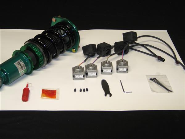
Here is part two of how to properly install EDFC motors (strut type, inverted shown). For this type of install is not as common as the last, but requires additional steps being that the motor is more exposed outside of the vehicle.

Additional tools you will need for this install is;

Small flat head screwdriver

1.5mm Allen wrench

Silicone sealant

For this install, it is recommended to do it with the damper off the vehicle and to remove the lower bracket for more clearance.

1st step: With a 1.5 mm Allen wrench, remove the click knob. Then you will need to use the 8mm click wrench to remove the click assembly. Once removed use the 3mm hex wrench to remove the original hex bolt from the damper.

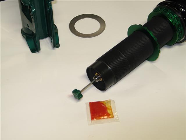
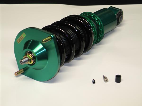
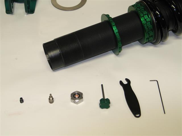
Parts removed; original hex bolt, click assembly, click knob. Along with tools used in removal process.

2nd Step: Add a small amount of supplied grease (orange bag) to the EDFC hex bolt threads and install the EDFC hex bolt until flush with the top of the piston rod. Be sure not to add threadlocker (red tube) to this part!

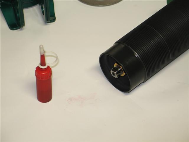
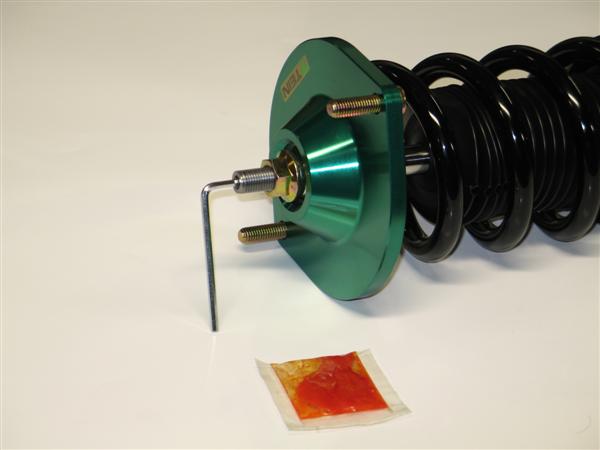
EDFC hex bolt installed with grease and flush with top of piston rod.

3rd Step: Add the supplied threadlocker (red tube) to the outside threads of the top of the piston rod. Please note, not a lot of threadlocker is needed nor does it need to cover all the threads.

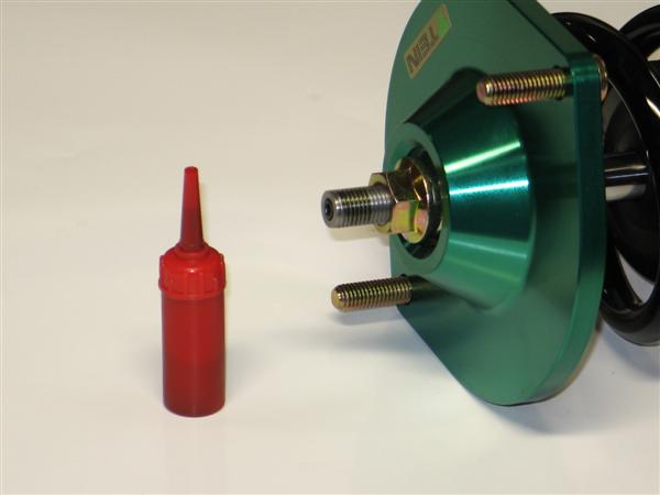
Area shown of where to apply the threadlocker to piston rod.

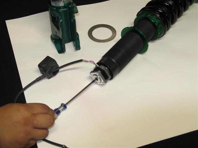
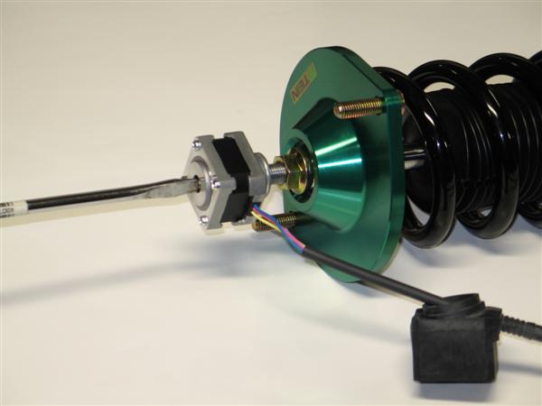
4th Step: Install the EDFC motor to the piston rod. This is the most important part and is sometimes easier with some help. What you need to do is place the EDFC motor shaft into the EDFC hex bolt. Now turn the EDFC motor 3 full rotations. At this point the EDFC motor should have started to thread onto the piston rod. Next, with your small flat head screwdriver, turn the top shaft of the EDFC motor 2 full turns clockwise (shown below). Continue to switch between turning the EDFC motor and top shaft in 3 or 2 specified full turn increments until the EDFC motor cannot turn anymore. The EDFC motor just needs to be hand tightened, not a lot of force is needed. Lastly turn the screw driver in both directions to ensure that the EDFC shaft can rotate freely.

NOTE: the EDFC motor or shaft does NOT need to be set to any particular position. Once the EDFC controller is turned on, it will self adjust.

With your small flat head screwdriver, this is the motor shaft of which you will be turning 2 full turns between 3 full turns of the EDFC motor.

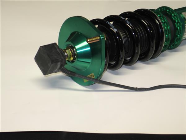
Now go ahead and bring the EDFC rubber dust cap up and cover the EDFC motor. Be careful not to rip the rubber cap. A little lubricant can be used to help install the dust cap. Be sure to confirm that the rubber cover is attached correctly. Otherwise dust or moisture can enter into the cover may shorten the life of the motor or cause trouble.

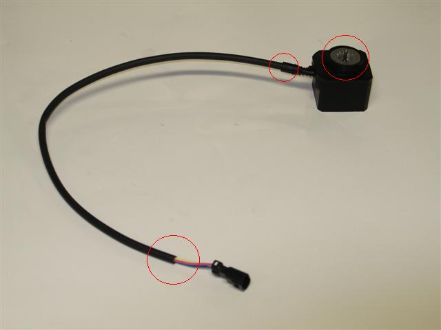
The last and most important step for this install would be to weatherproof the motors with a type of silicone sealant to areas shown in the picture below.

Be sure to add a silicone sealant to the circled areas to help protect the motors from getting damage from water.

Lastly use zip ties and tape to secure the EDFC wire. You want to avoid driveshafts and make sure there is plenty of slack for suspension movement. If there is limited space and you feel that the wire may come into contact with something, try to add a section of rubber hosing as added protection and periodically inspect the wiring.

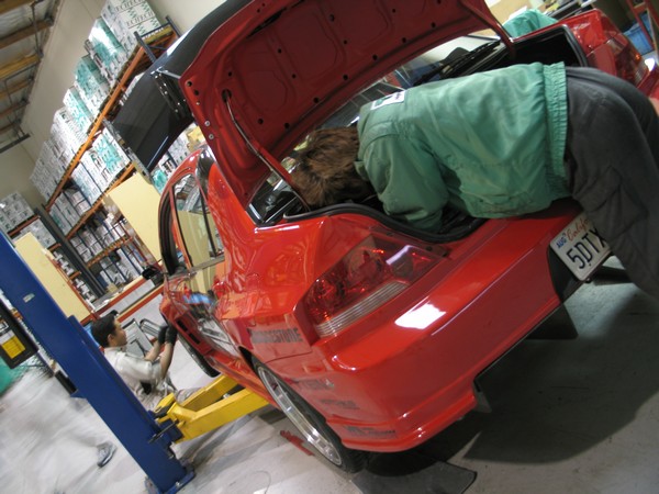
R&D Test Cars Needed.

Blog readers, greetings from the Tein USA Research and Development Section.

In the past, a majority of the blog posts done by R&D have been on vehicles which we had finished our testing on. We simply wanted to report on future products that you, the consumers, could look forward to.

As of late, however, we in R&D have run into a problem. We no longer have test cars to do testing on.

You see, with the continual release of new vehicles and models, there is no way for us to constantly look to just a few sources to provide us with these vehicles to do testing on.

We are completely reliant upon the consumers and enthusiasts, like yourself, to provide us with their personal vehicles to do the aforementioned testing on.

About the Testing itself:

Depending on the testing and the products being tested, the time frame that we require your vehicle for is usually 3-5 days.

Thinking of being without a vehicle for a bit of time may be a huge deterrent for many.

However, look on the bright side.

Free Suspension! Depending on the application, you may walk out with our lowering springs or you may walk out with  a set of our coilovers.

The installation will be professionally done by the R&D Engineers.


After the installation is finished we will perform a Basic Front-End Alignment and you’ll also be the first person to own the product.

If that sparks your interest and if you have the time to allow us with your vehicle, then check out this link and find out if your car is one of those that we are looking for. If you happen not to find your car on the list, no need to fret, check back every once in a while and we just may be in need of your car sometime down the line.

EDFC Motor Install

We get a lot of questions on how to properly install EDFC motors. So here are step by step directions on how to install an EDFC motor to your EDFC compatible coilover (shock type, non-inverted shown).  If not installed correctly, it could damage the EDFC motors and possibly the coilovers.

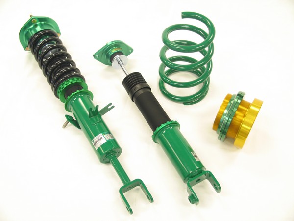
Layout of parts that are included with our EDFC Motor Kit and a few items from the controller kit.

Tools shown from left to right: threadlocker, grease, EDFC hex bolts, 8mm click wrench, 3mm allen wrench and zip ties.

** Additional parts you will need for this install is a small flat head screwdriver (not included)**

1st Step: Remove the add cap. Then use the 8mm click wrench to remove the click assembly. Once removed use the 3mm hex wrench to remove the original hex bolt from the damper.

Parts removed; original hex bolt, click assembly and add cap

2nd Step: Add a small amount of supplied grease (orange bag) to the EDFC hex bolt threads and install the EDFC hex bolt until flush with the top of the piston rod. Be sure not to add threadlocker (red tube) to this part!

EDFC hex bolt installed with grease and flush with top of piston rod.

3rd Step: Add the supplied threadlocker (red tube) to the outside threads of the top of the piston rod. Please note, not a lot of threadlock is needed nor does it need to cover all the threads.

Area shown of where to apply the threadlocker to piston rod.

4th Step: Install the EDFC motor to the top of the piston rod. This is the most important part and is sometimes easier with some help. What you need to do is place the EDFC motor shaft into the EDFC hex bolt. Now turn the EDFC motor 3 full rotations. At this point the EDFC motor should have started to thread onto the piston rod. Next, with your small flat head screwdriver, turn the top  shaft of the EDFC motor 2 full turns clockwise (shown below). Continue to switch  between turning the EDFC motor and top shaft in 3 or 2 specified full turn increments until the EDFC motor cannot turn anymore. The EDFC motor just needs to be hand tightened, not a lot of force is needed. Lastly turn the screw driver in both directions to ensure that the EDFC shaft can rotate freely.

NOTE: the EDFC motor or shaft does NOT need to be set to any particular position. Once the EDFC controller is turned on, it will self adjust.

With your small flat head screwdriver, this is the motor shaft of which you will be turning 2 full turns between 3 full turns of the EDFC motor.

Now go ahead and bring the EDFC rubber dust cap up and cover the EDFC motor. Be careful not to rip the rubber cap. A little lubricant can be used to help install the dust cap. Be sure to confirm that the rubber cover is attached correctly. Otherwise dust or moisture entering into the cover may shorten the lifetime of the motor or cause trouble. Use a zip tie to secure the tail of the dust cap and wire harness.

One coilover all finished.

Now its time for the remaining 3 coilovers.

Last thing to do would be once the coilovers are installed, you can use the zip ties to secure excess EDFC motor wires out of the way of getting damaged.
Please stay tuned, I will be continuing with EDFC motor install on strut type coilovers (Regular and Inverted) w/anti-tangle strut kit  and EDFC Controller wiring install.

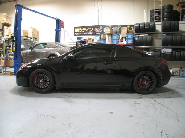
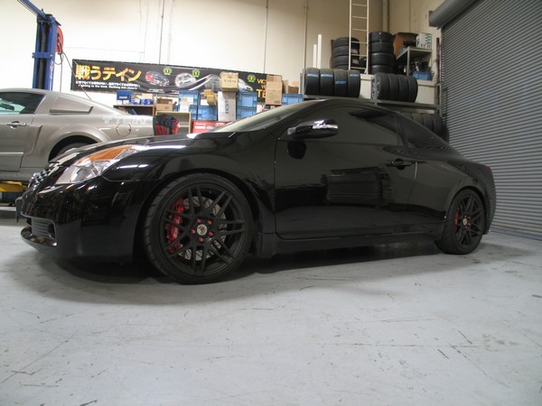
08+ Nissan Altima Coupe 3.5 Lowering Springs

Lowering Spring testing for the 08+ Nissan Altima Coupe 3.5L V6 Cylinder models has been completed.

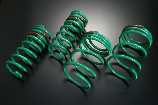
The S.Tech Springs, which will be available shortly, for the 3.5L V6 models.

The ride height drop for the 3.5L V6: Front -50mm and Rear -50mm,

The actual drop may vary by models due to the weight of different components (ie Transmission, Packages, etc.)

We will also be conducting Lowering Spring testing on the 2.5L I4 Coupe, 2.5L I4 Sedan, & 3.5L V6 Sedan soon.

Race Report: World Time Attack Challange

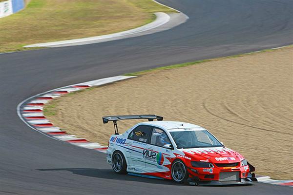
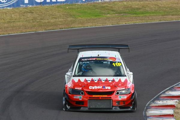
This past weekend was the World Time Attack Challenge held at the Eastern Creek Raceway in Australia. Although this event was new to my ears, it is unquestionably not new to the racing industry with many of the industries top manufactures and drivers present.

The car that really caught our attention was the world famous TEIN sponsored Mitsubishi Cyber Evo 9 driven by Mr. Eiji “Tarzan” Yamada. The Cyber Evo currently uses a custom valved, Super Racing coilover kit and previously used our HT kit.

The Cyber Evo took home first overall with a lap time of 1:30.5870 (0:01.2970 seconds faster than 2nd place).

All photos from World Time Attack website.

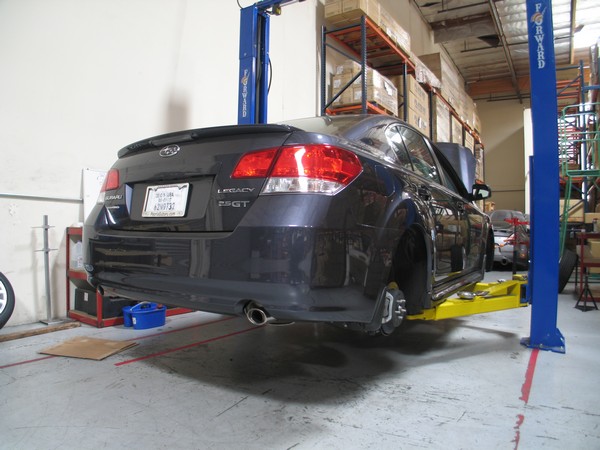
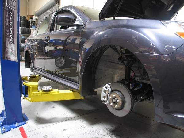
2010 2.5 Subaru Legacy Lowering Springs

S.Tech Spring testing on the 2010 2.5 Subaru Legacy has been completed.

Expect the ride height drop to be: Front -45mm and Rear -40mm

The actual drop may vary by models due to the weight of different components (ie Transmission, Packages, etc.)

Expect Mass Production units to be ready for sale in about 4 months time.

We will be testing Lowering Springs on the 3.6 Legacy soon.

We will also be testing coilovers in the near future.

2010 Mazda 3 Lowering Springs

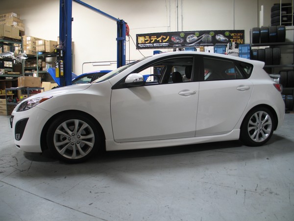
S.Tech Spring testing on the 2010 Mazda 3 has been completed.

For testing we used currently available TEIN Japan High.Tech Lowering Springs (gold colored springs).

The final US Spec S.Techs will be available sometime in the Summer of 2010. The specification will differ from the TEIN Japan spec springs we used for testing due to the differences between the US and JDM model vehicle.

Expect the ride height drop to be: Front -40mm and Rear -40mm

The actual drop may vary by models due to the weight of different components (ie Transmission, Packages, etc.)

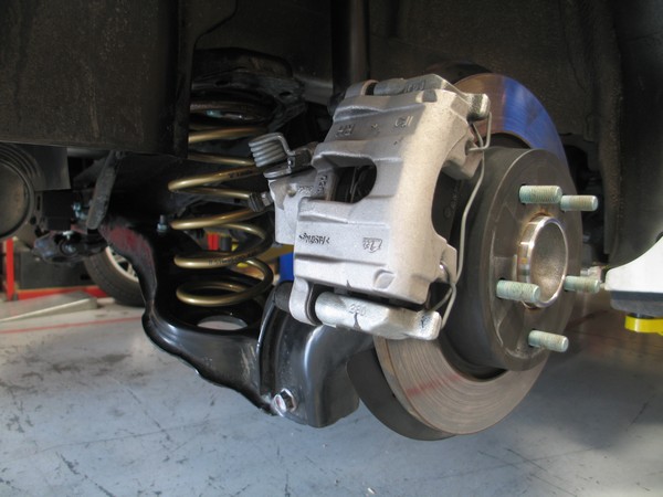
We take measurements at all positions of Compression and Rebound with and without the tires installed.

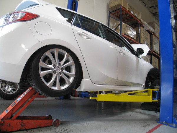
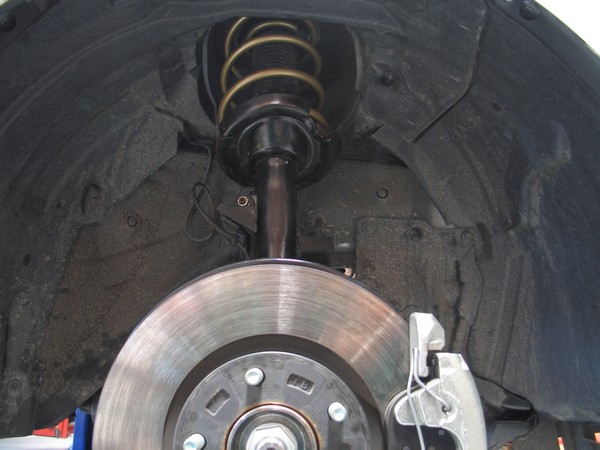
Above we have the tire installed and damper fully compressed to check for any clearance issues. Our products do lower your vehicle a considerable amount as compared to stock and we wouldn’t want any unnecessary damage to occur due to too low of a ride or too little clearance between parts.

Note: these are the Japanese Spec Lowering Springs, our final US Spec S.Techs will be Green.

2009 Mitsubishi Lancer GTS

S.Tech Spring testing on the 2009 2.4L Mitsubishi Lancer GTS has been completed.

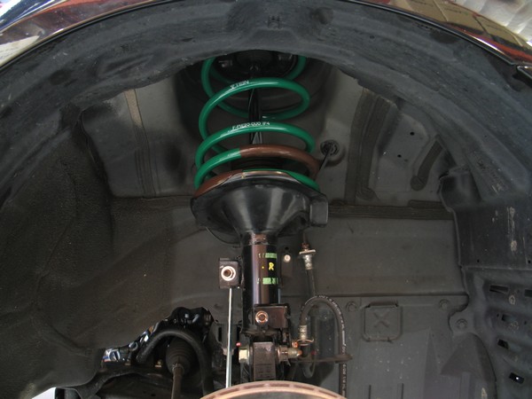
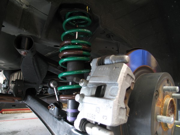
The S.Tech Springs Part # SKE20-AUB00, which have been available for other Lancer models, are now approved for use on the GTS as well.

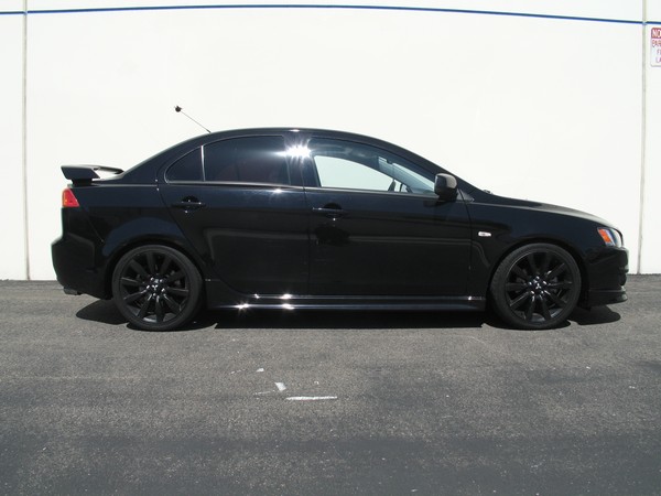
The ride height drop for the Lancer GTS: Front -51mm and Rear -30mm

The actual drop may vary by models due to the weight of different components (ie Transmission, Packages, etc.)

You too can have an aggressive drop that changes the image of the entire car, at a cost that won’t hurt your wallet. Contact you local Tein Dealer. http://www.tein.com/dealer_list/index.html

2010 V6 Acura TSX

Testing on the 2010 3.5L Acura TSX has been completed.

Basic Coilovers (Part # DSB90-LUSS2) and Super Street Coilovers (Part # DSB90-KUSS2) are Now Available.
These part numbers will fit both 3.5L V6 and 2.4L I4 models.

The ride height drop for the 3.5L V6: Front -36mm and Rear -35mm

The ride height drop for the 2.4L I4: Front -39mm and Rear -36mm

The actual drop may vary by models due to the weight of different components (ie Transmission, Technology Package, etc.)

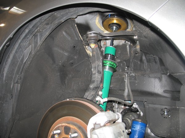
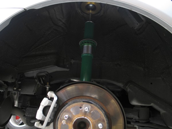
You will notice the dampers have been installed without the Springs, Bump Rubbers, and Dust Boots.
During one of our testing phases we check for the best possible ride height and clearance issues with our products and any of the vehicle’s suspension components, by taking measurements at various conditions of damper rebound and compression.

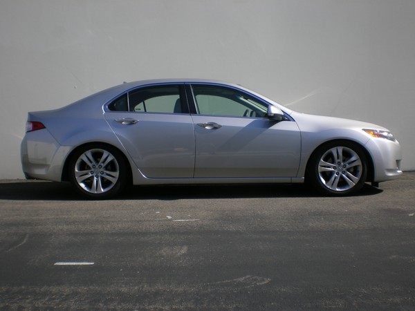
Here the car sits at recommended height with the OEM wheels. The tires tuck nicely giving an aggressive look.

Thanks to Honda Tuning magazine for letting us borrow their latest project vehicle. Be sure to check their website and issues when they hit the newsstand.

Hyundai Genesis Coupe 4 & 6 Cyl Testing

We recently finished testing of the 2010 Hyundai Genesis Coupe 4 & 6 Cylinder models.

The S.Tech Springs, which are Now Available, will fit both the 2.0L Turbo & 3.8L V6 models.

The ride height drop for the 2.0L Turbo: Front -30mm and Rear -30mm,

The ride height drop for the 3.8L V6: Front -27mm and Rear -36mm,

The actual drop will vary with different Package Models (ie Track, Grand Touring, Base, etc.) due to weight of different components.

BASIC coilovers are also in development at this time. Estimated availability is Summer 2010.

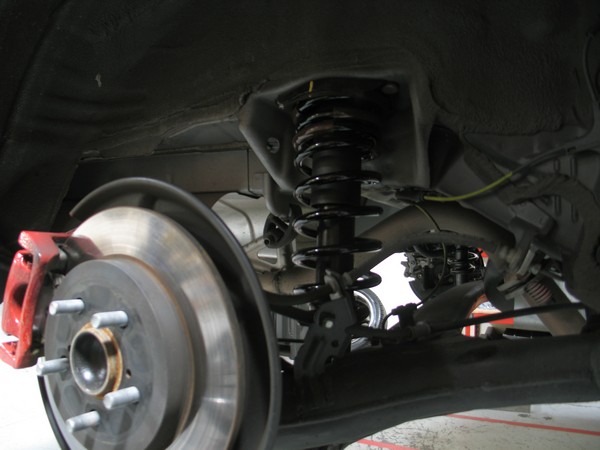
Front stock suspension with S.Tech Springs installed.

Rear stock suspension with S. Tech Springs installed.

Here we have the 2.0L Turbo Track Version lowered on the S. Tech Springs.


This is the 3.8L V6 lowered on S. Tech Springs.