TEIN MONO SPORT DAMPERS

Recently TEIN has been releasing there new updated version of our already popular coilover kits.

img04

The BASIC coilover kit has been updated and released as the STREET BASIS.

The Super Streets have been superseded by the STREET ADVANCE.

And our Flex damper has been superseded by the STREET FLEX.

All of these have been updated with new internal components and some minor changes to the outer portion as well. We’ve also been able to reduce MSRP a significant amount to make it much more affordable for our customers! You can find all the new product information through this link http://www.tein.com/products/index.html

bumprubber

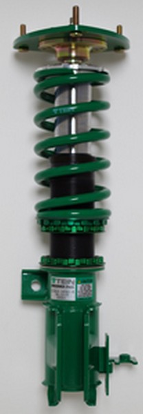
Well now it’s time for the Mono Flex to have a change as well.  They have been finding new ways to have one of the best suspensions in the market for a very reasonable price.  Starting in 2014 TEIN will be releasing two variations of the MONO Sport.

clearmodel

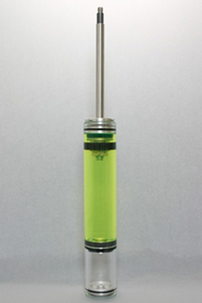
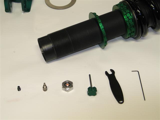
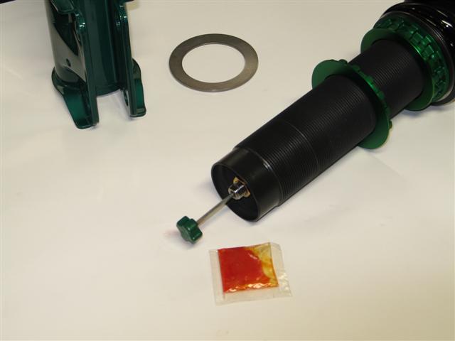
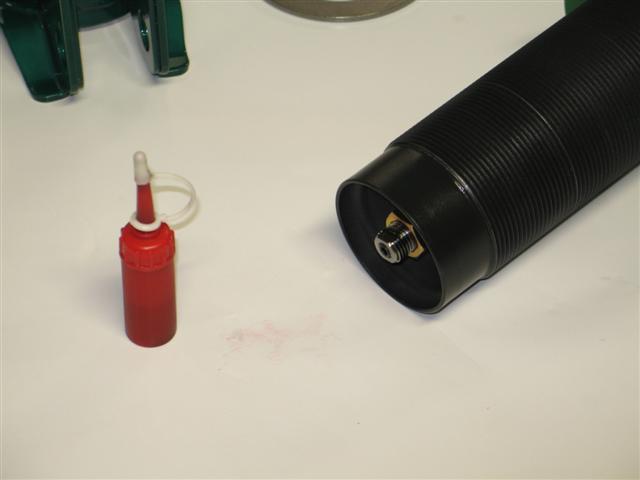
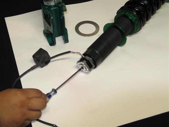
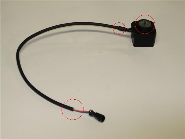
The MONO SPORT and the MONO SPORT TOURING Coilovers. Both lines will carry our newly designed Upright Strong Tube for strut type suspensions. With this newly design, it reduces friction using a revised internal lubrication method. With this design we are able to have the click assembly for the dampening force adjustment on the top, making the adjustments or installation of the optional EDFC/EDFC Active much easier.

img05


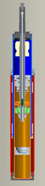
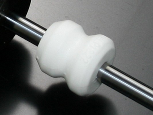
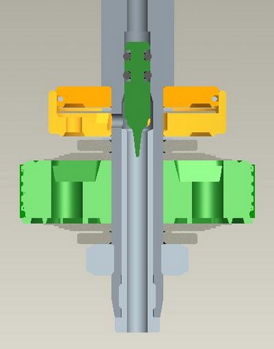
The system still offers the 16 levels of compression and rebound together, but now it is equipped with exclusively-designed “ADVANCE M.S.V.” With the use of “ADVANCE M.S.V.”, damping force adjustable range is made about three times wider, yet superior damping force characteristics are maintained in all parts to improve steering response, road ability and traction performance.

img06

These are just some of the few revisions done to the MONO Sport line for further information on the system please follow this link. http://www.tein.co.jp/e/products/mono_sport.html

EDFC Motor Install Part 2

Here is part two of how to properly install EDFC motors (strut type, inverted shown). For this type of install is not as common as the last, but requires additional steps being that the motor is more exposed outside of the vehicle.

Additional tools you will need for this install is;

Small flat head screwdriver

1.5mm Allen wrench

Silicone sealant

For this install, it is recommended to do it with the damper off the vehicle and to remove the lower bracket for more clearance.

1st step: With a 1.5 mm Allen wrench, remove the click knob. Then you will need to use the 8mm click wrench to remove the click assembly. Once removed use the 3mm hex wrench to remove the original hex bolt from the damper.

Parts removed; original hex bolt, click assembly, click knob. Along with tools used in removal process.

2nd Step: Add a small amount of supplied grease (orange bag) to the EDFC hex bolt threads and install the EDFC hex bolt until flush with the top of the piston rod. Be sure not to add threadlocker (red tube) to this part!

EDFC hex bolt installed with grease and flush with top of piston rod.

3rd Step: Add the supplied threadlocker (red tube) to the outside threads of the top of the piston rod. Please note, not a lot of threadlocker is needed nor does it need to cover all the threads.

Area shown of where to apply the threadlocker to piston rod.

4th Step: Install the EDFC motor to the piston rod. This is the most important part and is sometimes easier with some help. What you need to do is place the EDFC motor shaft into the EDFC hex bolt. Now turn the EDFC motor 3 full rotations. At this point the EDFC motor should have started to thread onto the piston rod. Next, with your small flat head screwdriver, turn the top shaft of the EDFC motor 2 full turns clockwise (shown below). Continue to switch between turning the EDFC motor and top shaft in 3 or 2 specified full turn increments until the EDFC motor cannot turn anymore. The EDFC motor just needs to be hand tightened, not a lot of force is needed. Lastly turn the screw driver in both directions to ensure that the EDFC shaft can rotate freely.

NOTE: the EDFC motor or shaft does NOT need to be set to any particular position. Once the EDFC controller is turned on, it will self adjust.

With your small flat head screwdriver, this is the motor shaft of which you will be turning 2 full turns between 3 full turns of the EDFC motor.

Now go ahead and bring the EDFC rubber dust cap up and cover the EDFC motor. Be careful not to rip the rubber cap. A little lubricant can be used to help install the dust cap. Be sure to confirm that the rubber cover is attached correctly. Otherwise dust or moisture can enter into the cover may shorten the life of the motor or cause trouble.

The last and most important step for this install would be to weatherproof the motors with a type of silicone sealant to areas shown in the picture below.

Be sure to add a silicone sealant to the circled areas to help protect the motors from getting damage from water.

Lastly use zip ties and tape to secure the EDFC wire. You want to avoid driveshafts and make sure there is plenty of slack for suspension movement. If there is limited space and you feel that the wire may come into contact with something, try to add a section of rubber hosing as added protection and periodically inspect the wiring.