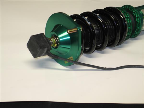
EDFC Error Codes Explained

Hey whats up every one. Since Ryan has posted proper EDFC motor installation, I’ll give everyone tips on solving any error codes you may encounter after installation or later on down the road.

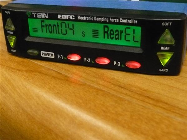
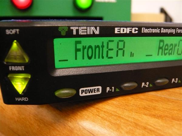
A common misconception on the EDFC display are the codes. There are three different error codes: ER, EL and EE. A fair amount of people seem to think that there is “EA” error code = Error All. The actual code is “ER” , error right side motor on either the front side or the rear side. Yeah, it looks like an “A” but that is a “R”. The below image shows an error for the right front side since the error is displayed for Front.

Next, code “EL” which means error left. In the image below the error is on the rear left side because the “EL” is displayed for Rear.

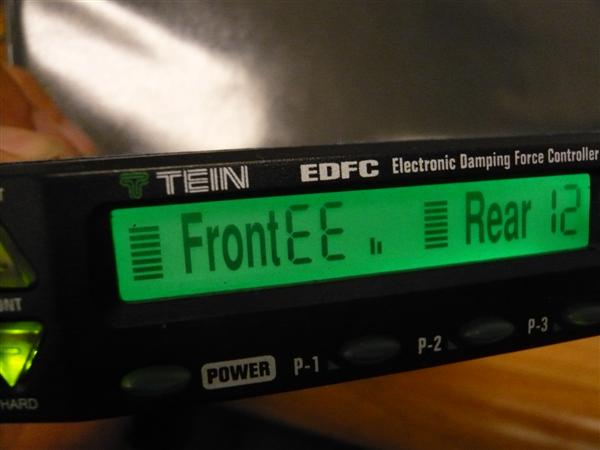
Lastly, code “EE” which means error on both right and left. In the image below, error right and left for the Front.

The error codes can be caused from several areas on or around the wiring and components. We will start with the most common source of the errors.

1) Harness plug between EDFC motor and EDFC wiring harness.

The terminals (pins) inside the plug can be pushed out slightly causing the connection to be lost.

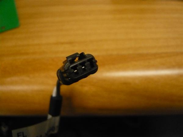
You can see on this male connector that the pin on the right has been pushed back not allowing a connection to be made.

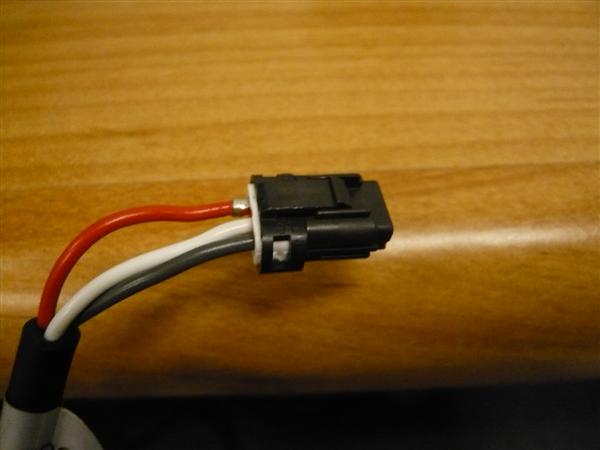
You can see the red wire on this female connector has gotten de-pinned.

Fix the problem by pushing the wire back into the plug and let it re-seat itself. When connecting the two plugs, hold the plug and wiring to ensure the pins do not get pushed out again.

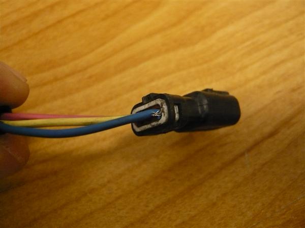
If the wire has some stray or frayed wire not really holding on to the terminal, I recommend replacing the whole cable or motor to avoid damaging the control unit.

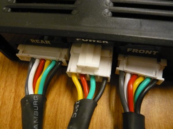
2) The harness plugs on the back side of the control unit are not plugged in completely. The thin white plugs for front and rear EDFC harnesses need to be plugged into the back of the controller perfectly. It should not be tilted as shown in the image below. So if your EDFC harness is pulling the connector to one side, it can easily cause an error.

Left and center plug correctly plugged in while the right plug is not fully connected.

Fix the problem by re-adjusting the harness. Changing the wiring route or using zip ties to secure the harness may help.

3) Frayed or damaged wiring. This is not likely on a brand new EDFC install. More the case on an EDFC system that suddenly starts throwing error codes. Depending on how the wiring was run throughout the vehicle the wiring could have become frayed or pinched over time thus causing damage to the harness and loss in connection.

The fix is to determine the problem area and repair or replace the wiring.

In a future post we will go over some trouble shooting tips for isolating EDFC problems.

Replacement parts can be purchased from the TEIN Online Shop or through a TEIN Authorized Dealer. To find the part number for the needed part please refer to the EDFC installation manual. If you no longer have your manual click the following link. If you have an older Silver EDFC Control unit the wiring and motors are different so please contact us for the correct part number – contact.

EDFC Motor Install Part 2

Here is part two of how to properly install EDFC motors (strut type, inverted shown). For this type of install is not as common as the last, but requires additional steps being that the motor is more exposed outside of the vehicle.

Additional tools you will need for this install is;

Small flat head screwdriver

1.5mm Allen wrench

Silicone sealant

For this install, it is recommended to do it with the damper off the vehicle and to remove the lower bracket for more clearance.

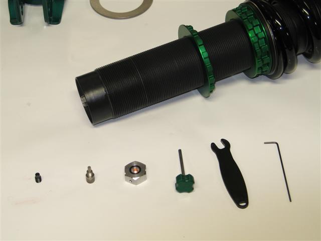
1st step: With a 1.5 mm Allen wrench, remove the click knob. Then you will need to use the 8mm click wrench to remove the click assembly. Once removed use the 3mm hex wrench to remove the original hex bolt from the damper.

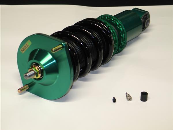
Parts removed; original hex bolt, click assembly, click knob. Along with tools used in removal process.

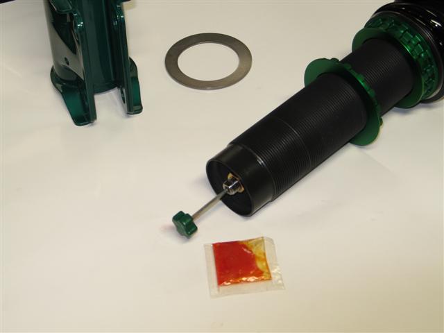
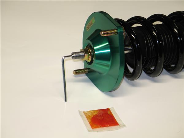
2nd Step: Add a small amount of supplied grease (orange bag) to the EDFC hex bolt threads and install the EDFC hex bolt until flush with the top of the piston rod. Be sure not to add threadlocker (red tube) to this part!

EDFC hex bolt installed with grease and flush with top of piston rod.

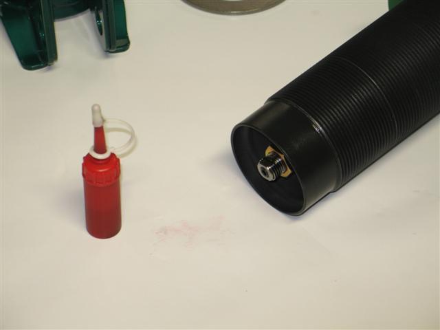
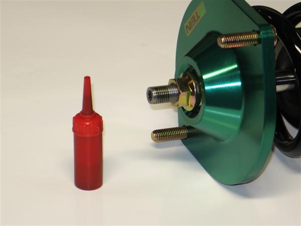
3rd Step: Add the supplied threadlocker (red tube) to the outside threads of the top of the piston rod. Please note, not a lot of threadlocker is needed nor does it need to cover all the threads.

Area shown of where to apply the threadlocker to piston rod.

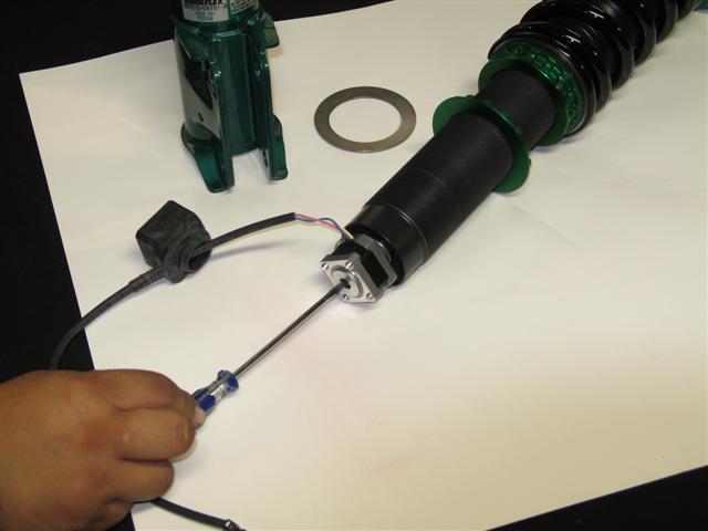
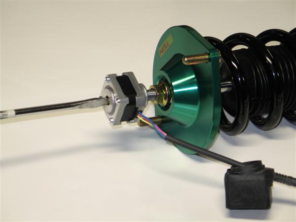
4th Step: Install the EDFC motor to the piston rod. This is the most important part and is sometimes easier with some help. What you need to do is place the EDFC motor shaft into the EDFC hex bolt. Now turn the EDFC motor 3 full rotations. At this point the EDFC motor should have started to thread onto the piston rod. Next, with your small flat head screwdriver, turn the top shaft of the EDFC motor 2 full turns clockwise (shown below). Continue to switch between turning the EDFC motor and top shaft in 3 or 2 specified full turn increments until the EDFC motor cannot turn anymore. The EDFC motor just needs to be hand tightened, not a lot of force is needed. Lastly turn the screw driver in both directions to ensure that the EDFC shaft can rotate freely.

NOTE: the EDFC motor or shaft does NOT need to be set to any particular position. Once the EDFC controller is turned on, it will self adjust.

With your small flat head screwdriver, this is the motor shaft of which you will be turning 2 full turns between 3 full turns of the EDFC motor.

Now go ahead and bring the EDFC rubber dust cap up and cover the EDFC motor. Be careful not to rip the rubber cap. A little lubricant can be used to help install the dust cap. Be sure to confirm that the rubber cover is attached correctly. Otherwise dust or moisture can enter into the cover may shorten the life of the motor or cause trouble.

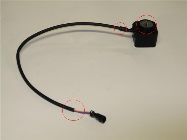
The last and most important step for this install would be to weatherproof the motors with a type of silicone sealant to areas shown in the picture below.

Be sure to add a silicone sealant to the circled areas to help protect the motors from getting damage from water.

Lastly use zip ties and tape to secure the EDFC wire. You want to avoid driveshafts and make sure there is plenty of slack for suspension movement. If there is limited space and you feel that the wire may come into contact with something, try to add a section of rubber hosing as added protection and periodically inspect the wiring.

EDFC Motor Install

We get a lot of questions on how to properly install EDFC motors. So here are step by step directions on how to install an EDFC motor to your EDFC compatible coilover (shock type, non-inverted shown).  If not installed correctly, it could damage the EDFC motors and possibly the coilovers.

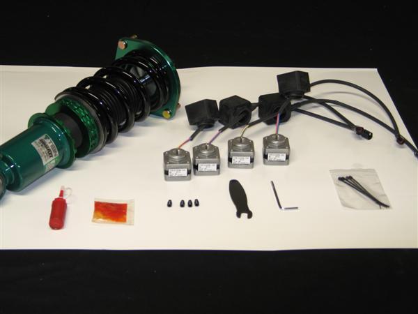
Layout of parts that are included with our EDFC Motor Kit and a few items from the controller kit.

Tools shown from left to right: threadlocker, grease, EDFC hex bolts, 8mm click wrench, 3mm allen wrench and zip ties.

** Additional parts you will need for this install is a small flat head screwdriver (not included)**

1st Step: Remove the add cap. Then use the 8mm click wrench to remove the click assembly. Once removed use the 3mm hex wrench to remove the original hex bolt from the damper.

Parts removed; original hex bolt, click assembly and add cap

2nd Step: Add a small amount of supplied grease (orange bag) to the EDFC hex bolt threads and install the EDFC hex bolt until flush with the top of the piston rod. Be sure not to add threadlocker (red tube) to this part!

EDFC hex bolt installed with grease and flush with top of piston rod.

3rd Step: Add the supplied threadlocker (red tube) to the outside threads of the top of the piston rod. Please note, not a lot of threadlock is needed nor does it need to cover all the threads.

Area shown of where to apply the threadlocker to piston rod.

4th Step: Install the EDFC motor to the top of the piston rod. This is the most important part and is sometimes easier with some help. What you need to do is place the EDFC motor shaft into the EDFC hex bolt. Now turn the EDFC motor 3 full rotations. At this point the EDFC motor should have started to thread onto the piston rod. Next, with your small flat head screwdriver, turn the top  shaft of the EDFC motor 2 full turns clockwise (shown below). Continue to switch  between turning the EDFC motor and top shaft in 3 or 2 specified full turn increments until the EDFC motor cannot turn anymore. The EDFC motor just needs to be hand tightened, not a lot of force is needed. Lastly turn the screw driver in both directions to ensure that the EDFC shaft can rotate freely.

NOTE: the EDFC motor or shaft does NOT need to be set to any particular position. Once the EDFC controller is turned on, it will self adjust.

With your small flat head screwdriver, this is the motor shaft of which you will be turning 2 full turns between 3 full turns of the EDFC motor.

Now go ahead and bring the EDFC rubber dust cap up and cover the EDFC motor. Be careful not to rip the rubber cap. A little lubricant can be used to help install the dust cap. Be sure to confirm that the rubber cover is attached correctly. Otherwise dust or moisture entering into the cover may shorten the lifetime of the motor or cause trouble. Use a zip tie to secure the tail of the dust cap and wire harness.

One coilover all finished.

Now its time for the remaining 3 coilovers.

Last thing to do would be once the coilovers are installed, you can use the zip ties to secure excess EDFC motor wires out of the way of getting damaged.
Please stay tuned, I will be continuing with EDFC motor install on strut type coilovers (Regular and Inverted) w/anti-tangle strut kit  and EDFC Controller wiring install.