EDFC Fitment Check

Back again with some more useful tech info this time for EDFC fitment verification.

We are always receiving calls regarding EDFC fitment on older kits or kits which may not have any details of EDFC compatibility. I was able to obtain some info on some specific areas ,clearances, and measurements that should be focused on when checking for compatibility.


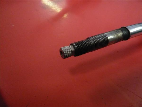
Checking piston shaft compatibility

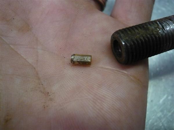
Inspect the top threaded portion of the of the dampers piston shaft making sure that the shaft is threaded all the way to the top of the shaft. Some shafts may have the flat machined edges, but the threads continue on the other rounded sides. Those can still work. The other type as shown below would have an area around the top of the piston shaft with no threads which not allow the EDFC motor to mount up.


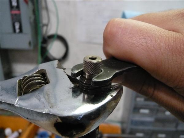
Measuring piston shaft thread amount

Taking a measurement of the same area which protrudes out from the mount, measuring from the edge of the nut to the tip of the shaft. If the measurement is more than 7mm in length, then the EDFC would have enough space to bolt on. Any less and there would not be sufficient space for the motor.


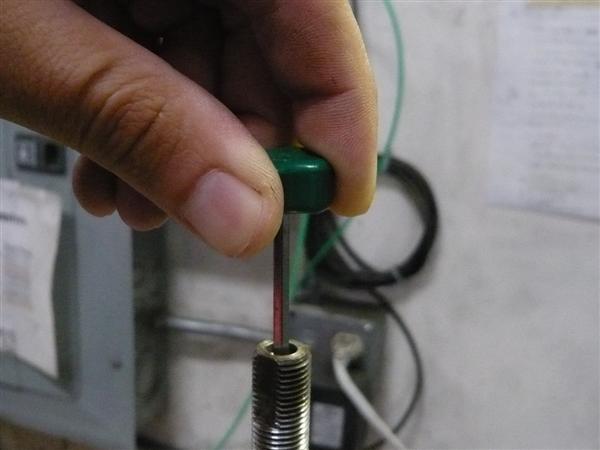
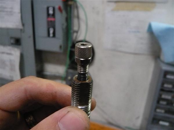
Checking compartment space for EDFC motor

 Taking a measurement from the top of the click assembly a vertical measurement of over 24mm as well as a 50mm horizontal measurement using the center of the piston shaft as the center point. Any clearances less than those detailed would interfere with either the hood or other engine compartment components and/or interior.


Caution! When checking these areas please note that the measurements provided above are the minimum required clearances for the EDFC motor installation. Please keep in mind that depending on the mount type used on the damper kit, the motor might move vertically which may require further clearance. Modifications and/or removal of supportive device around piston shaft top, insulator and/or interior might be required to allow for fitment. EDFC, in conjunction with any tower bars/strut bars may not allow enough clearance across the piston shaft for certain applications. Installation of the EDFC on any vehicles/ dampers on which TEIN had not confirmed fitment compatibility should be done at your own discretion. TEIN assumes no responsibility for any damaged and warranty void for such installations.

 Always exercise caution when trying to install the EDFC units on your application whether the kit has been confirmed for fitment or the guide detailed above is being used to determine fitment. Uncertain of the installation? You can always take a look back at an early post for the EDFC installation for help.

http://teinusa-blog.com/edfc-motor-install/

Quick Click Fixes

The TEIN adjustable damping force coilover click adjuster is commonly misdiagnosed part. Misdiagnosed because many customers with stuck or broken adjustment knobs (click assembly) think that repair or replacement requires the damper to be sent to us for repair. For many stuck adjustment knobs a new replacement click assembly is not required. Here are some tips you can use if you encounter a stuck click adjuster or are looking to replace a broken unit.

Click adjuster or Adjustment knob may be located at the top and/or bottom of your coilover depending on type.

Stuck or seized Click Assembly

A click assembly that does not turn smoothly or turn at all may be a quick and easy fix IF there is enough space to work on the unit.  The problem is usually caused by debris getting lodged in between the knob and knob base.  Between the two halves there is a spring loaded ball bearing (located under the knob) moves into machined divets (located on the knob base). Debris can stop the movement of the ball or become lodged into the divets. Another cause could be moisture build up inside the coilover piston rod causing the small hex bolt to seize. THE FIXES:

1) Try to use compressed air to dislodge any dirt or debris between the two halves of the click assembly.

2) Remove the click assembly. Then clean and re-lubricate the hex bolt.

A TEIN Click Assembly Wrench (black), Part #SST01-F1126, MSRP $5 can be purchased from our online store.

To do the second fix you will need a TEIN 8mm wrench or a modified standard 8mm wrench (grinded to 3mm thickness). Use the 8mm thin wrench to remove the click assembly (see image below). A crescent wrench can be used to keep the piston shaft from spinning (be sure not to damage the threads on the piston shaft). Next use the click adjustment tool or a 3mm allen wrench to remove the hex bolt (see image below).

Using the TEIN Click Assembly Wrench and a crescent wrench to remove the click assembly.

After the click assembly is removed use the click adjustment tool to remove the small hex screw inside the piston shaft.

Both click assembly and hex bolt can be cleaned with some mild parts cleaner.

Scroll to the bottom on instructions for re-assembly.

Note: TEIN coilover kits do include a rubber add cap to prevent moisture and debris from forming but I would still recommend checking the assembly once in a while.

Replacing a broken click assembly

The click assembly can break in two different places. One, the top half of the knob (knurled section). Second, is the bottom tip of the click assembly (resembles hex bit or allen key).

Replacing a broken click assembly may be a little more work if bottom tip has broken off inside the piston shaft. This may require the coilover to be removed from the vehicle if it cannot be easily removed.

First remove the click assembly using the same method stated above.

This is what the click assembly looks like when the top half is missing.

After the click assembly is removed inspect it to see if the bottom tip is intact or not.

This is a complete Click Assembly (silver) with Hex Bolt (black).

You can see the click assembly has a knurled top section, 8mm hex and threaded section and bottom 3mm hex tip.

This exact assembly can be purchased on our online shop, Part #SPS12-G0047.

If the bottom tip has broken off extract it with a pick tool or magnet. If the tip is stuck in the hex screw you may need to use lubricant and lightly tap the piston shaft to help dislodge it. In this case the plastic end of a screw driver or plastic hammer works well. Be careful when using a tool to extract the lodged piece as the inner and outer threads can be damaged. Use Caution.

Broken piece of the bottom tip of the click assembly.

Installation of Click Assembly and Hex Bolt

With the click assembly off the piston shaft and hex bolt removed. Clean and lightly lube the threads inside the piston rod with light grease. When installing the new click assembly and hex bolt, you can use the click assembly, click adjustment tool, or allen key to thread in the hex bolt. We recommended to insert the hex bolt about 3/4 of the way to allow the click assembly to catch the hex.

Insert the bottom tip of the click assembly into the hex bolt and screw in.

Tightening the click assembly to 12 inch pounds torque or snug (do not over torque).

Check to make sure the click knob can rotate smoothly in both directions. Then adjust click knob to desired setting. Remember turn the click knob to full clockwise position (Zero setting or stiffest setting), then turn counter-clockwise to desired position (16 setting or softest position). Click assembly may click more than 16 times but going past 16 clicks does nothing for adjustment and repeatedly exceeding 16 clicks may cause internal shock damage.

If the click assembly or hex bolt can not be removed it may be required to send in the damper to determine condition and have the parts removed. Worst case scenario would be a new piston rod with overhaul (this is a rare case scenario).