Overhaul Results

Hello from the TEIN R&D Department. Some, if not most, of you own a set of our dampers. If it so happens that you do indeed own and use a set of Tein Dampers, sometime down the line the damper is going to need an overhaul.

Whether the damper is leaking or just not performing like it used to, we have all your Overhaul needs covered. Follow this link for some basic prices and information regarding your Overhaul Service.

Here, we’ll be using one of our Overhaul Customer’s dampers to show you what normally goes on during our Overhaul Service.

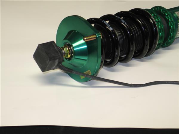
We can see that this customer’s damper has been leaking oil and has accumulated some dirt while being driven. (Remember everyone, check the conditions of your dampers often. If you see it beginning to leak send it in for servicing. Continued use of an already worn out damper can only do more harm.)

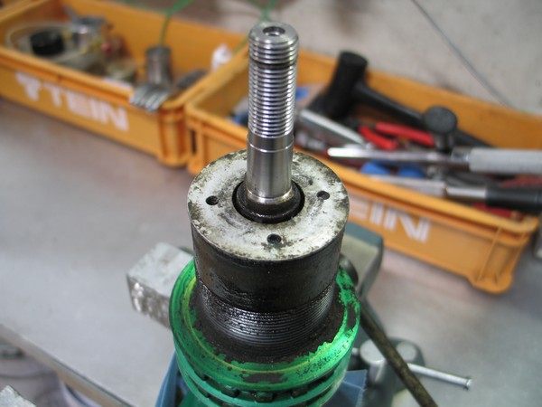
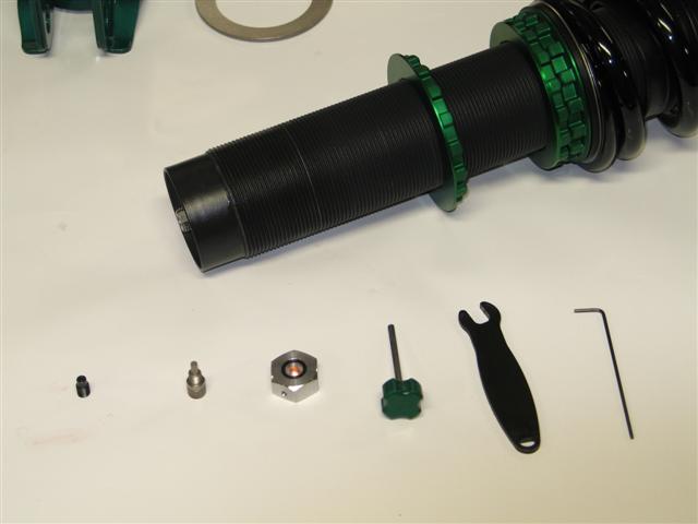
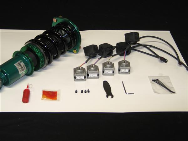
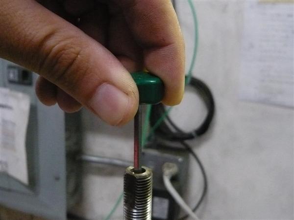
We’ve disassembled the damper and the parts are going to be washed.

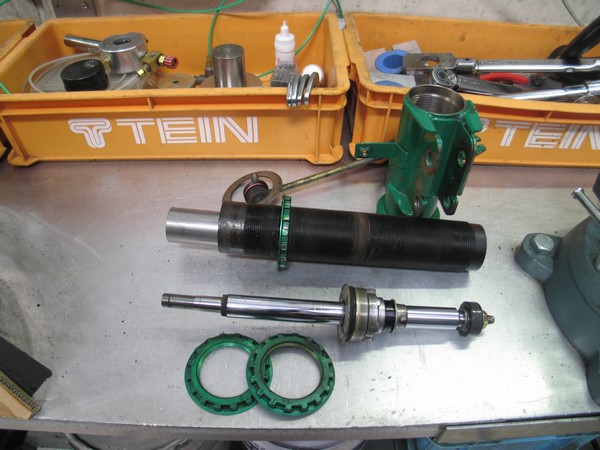
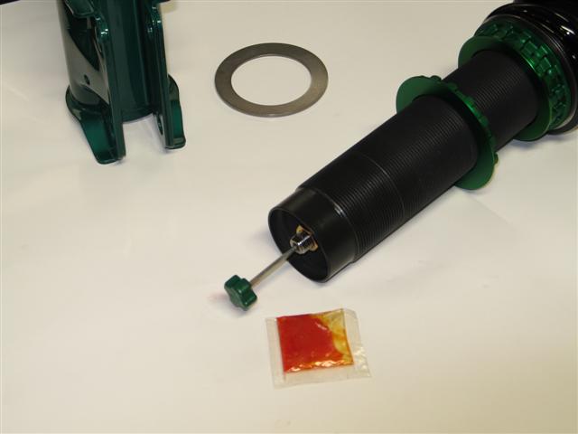
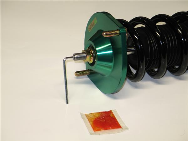
One of the easiest ways for us to determine how badly your dampers needed servicing is by looking at the overall color and quantity of the oil that comes out of the damper. The oil on the Left is new shock absorber oil, and the oil on the left is what came out of the damper, you can see the color difference between the two. When compared with the amount of oil the damper should have had, the actual amount that came out is quite low. (Driving a shock absorber with little to no oil will have the same consequences as driving your engine with no oil, inner components will begin to wear down and need replacing, or in the worst cases we’ve seen, the dampers are completely irreparable.)

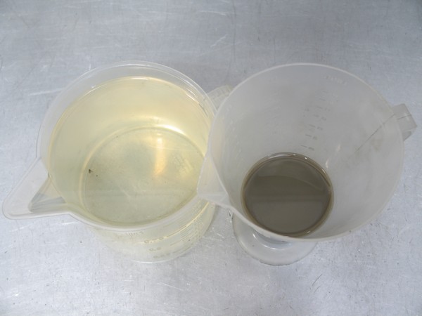
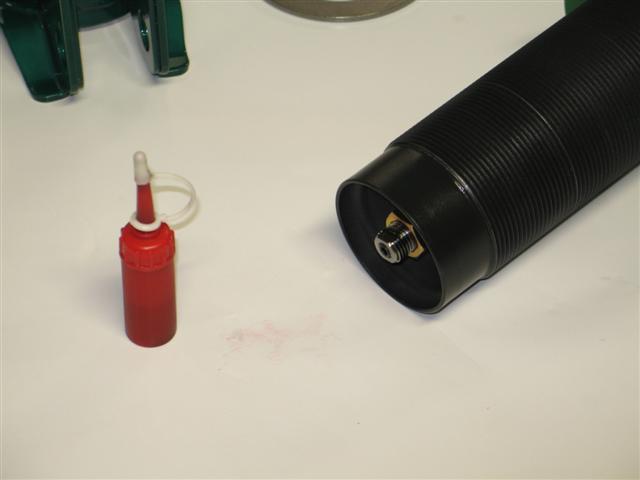
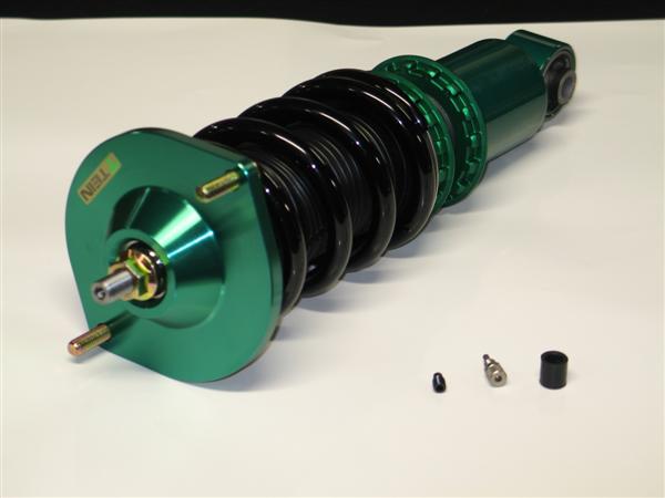
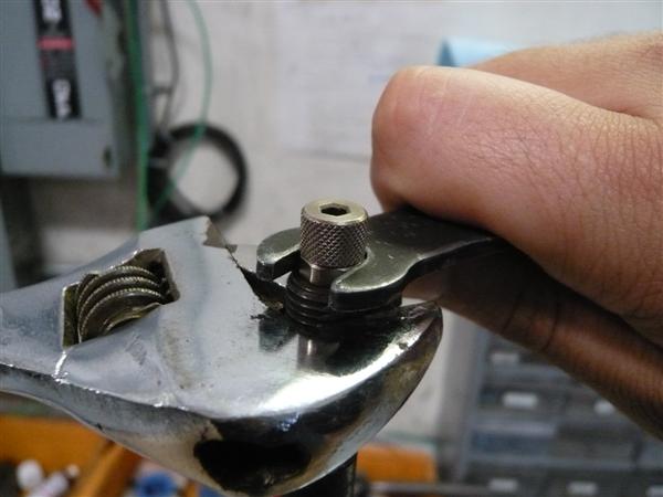
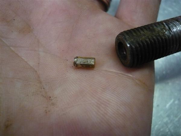
After the parts are washed and inspected further, worn down parts will be replaced.

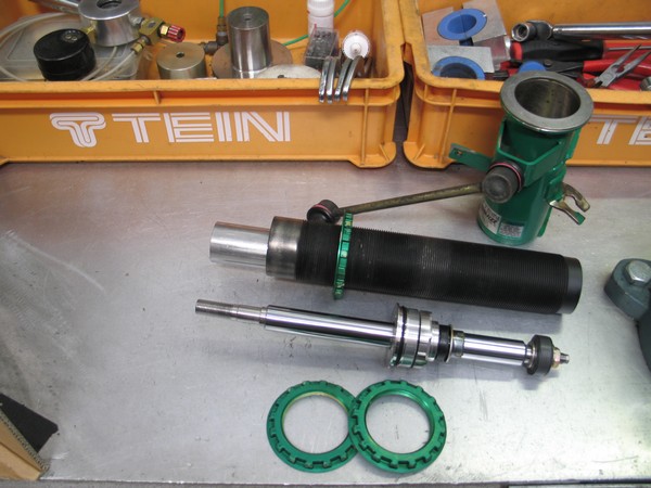
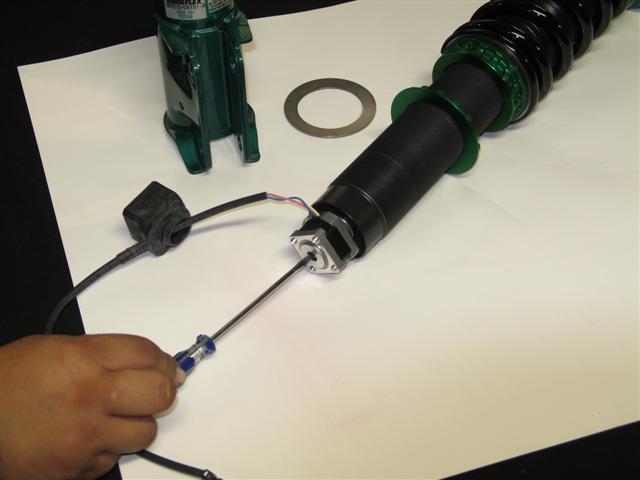
After everything is put back together you have a damper that performs just as it did out of the box and looks almost like it did out of the box. (Our dampers are originally powder coated. If the paint is beginning to fade or peel, to get it back to looking like brand new the damper would require a re-powder coating service. Unfortunately, we do not have that service available.)

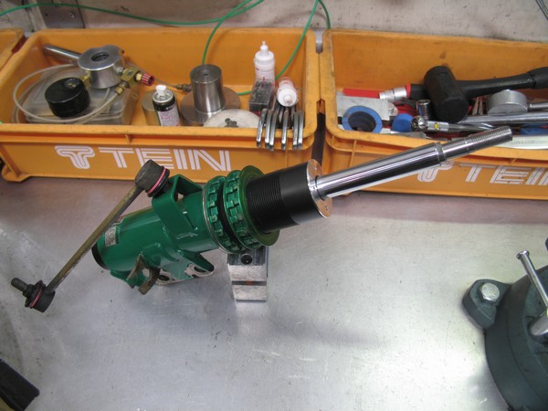
Our recommended Overhaul Service interval is 3 Years/36,000 Miles if the damper is used only for daily driving/paved road use. If your dampers see track time or off-road time then your recommended Service Interval will be shorter. Vice versa if the dampers are used on a “Saturday Night or Weekend Special” car then your Service Interval will be longer.

Bottom line, check your dampers’ condition often. If you see oil or if they’re not performing like they used to then send them on in. We’ll make them look and feel like new.

EDFC Error Codes Explained

Hey whats up every one. Since Ryan has posted proper EDFC motor installation, I’ll give everyone tips on solving any error codes you may encounter after installation or later on down the road.

A common misconception on the EDFC display are the codes. There are three different error codes: ER, EL and EE. A fair amount of people seem to think that there is “EA” error code = Error All. The actual code is “ER” , error right side motor on either the front side or the rear side. Yeah, it looks like an “A” but that is a “R”. The below image shows an error for the right front side since the error is displayed for Front.

Next, code “EL” which means error left. In the image below the error is on the rear left side because the “EL” is displayed for Rear.

Lastly, code “EE” which means error on both right and left. In the image below, error right and left for the Front.

The error codes can be caused from several areas on or around the wiring and components. We will start with the most common source of the errors.

1) Harness plug between EDFC motor and EDFC wiring harness.

The terminals (pins) inside the plug can be pushed out slightly causing the connection to be lost.

You can see on this male connector that the pin on the right has been pushed back not allowing a connection to be made.

You can see the red wire on this female connector has gotten de-pinned.

Fix the problem by pushing the wire back into the plug and let it re-seat itself. When connecting the two plugs, hold the plug and wiring to ensure the pins do not get pushed out again.

If the wire has some stray or frayed wire not really holding on to the terminal, I recommend replacing the whole cable or motor to avoid damaging the control unit.

2) The harness plugs on the back side of the control unit are not plugged in completely. The thin white plugs for front and rear EDFC harnesses need to be plugged into the back of the controller perfectly. It should not be tilted as shown in the image below. So if your EDFC harness is pulling the connector to one side, it can easily cause an error.

Left and center plug correctly plugged in while the right plug is not fully connected.

Fix the problem by re-adjusting the harness. Changing the wiring route or using zip ties to secure the harness may help.

3) Frayed or damaged wiring. This is not likely on a brand new EDFC install. More the case on an EDFC system that suddenly starts throwing error codes. Depending on how the wiring was run throughout the vehicle the wiring could have become frayed or pinched over time thus causing damage to the harness and loss in connection.

The fix is to determine the problem area and repair or replace the wiring.

In a future post we will go over some trouble shooting tips for isolating EDFC problems.

Replacement parts can be purchased from the TEIN Online Shop or through a TEIN Authorized Dealer. To find the part number for the needed part please refer to the EDFC installation manual. If you no longer have your manual click the following link. If you have an older Silver EDFC Control unit the wiring and motors are different so please contact us for the correct part number – contact.

EDFC Motor Install Part 2

Here is part two of how to properly install EDFC motors (strut type, inverted shown). For this type of install is not as common as the last, but requires additional steps being that the motor is more exposed outside of the vehicle.

Additional tools you will need for this install is;

Small flat head screwdriver

1.5mm Allen wrench

Silicone sealant

For this install, it is recommended to do it with the damper off the vehicle and to remove the lower bracket for more clearance.

1st step: With a 1.5 mm Allen wrench, remove the click knob. Then you will need to use the 8mm click wrench to remove the click assembly. Once removed use the 3mm hex wrench to remove the original hex bolt from the damper.

Parts removed; original hex bolt, click assembly, click knob. Along with tools used in removal process.

2nd Step: Add a small amount of supplied grease (orange bag) to the EDFC hex bolt threads and install the EDFC hex bolt until flush with the top of the piston rod. Be sure not to add threadlocker (red tube) to this part!

EDFC hex bolt installed with grease and flush with top of piston rod.

3rd Step: Add the supplied threadlocker (red tube) to the outside threads of the top of the piston rod. Please note, not a lot of threadlocker is needed nor does it need to cover all the threads.

Area shown of where to apply the threadlocker to piston rod.

4th Step: Install the EDFC motor to the piston rod. This is the most important part and is sometimes easier with some help. What you need to do is place the EDFC motor shaft into the EDFC hex bolt. Now turn the EDFC motor 3 full rotations. At this point the EDFC motor should have started to thread onto the piston rod. Next, with your small flat head screwdriver, turn the top shaft of the EDFC motor 2 full turns clockwise (shown below). Continue to switch between turning the EDFC motor and top shaft in 3 or 2 specified full turn increments until the EDFC motor cannot turn anymore. The EDFC motor just needs to be hand tightened, not a lot of force is needed. Lastly turn the screw driver in both directions to ensure that the EDFC shaft can rotate freely.

NOTE: the EDFC motor or shaft does NOT need to be set to any particular position. Once the EDFC controller is turned on, it will self adjust.

With your small flat head screwdriver, this is the motor shaft of which you will be turning 2 full turns between 3 full turns of the EDFC motor.

Now go ahead and bring the EDFC rubber dust cap up and cover the EDFC motor. Be careful not to rip the rubber cap. A little lubricant can be used to help install the dust cap. Be sure to confirm that the rubber cover is attached correctly. Otherwise dust or moisture can enter into the cover may shorten the life of the motor or cause trouble.

The last and most important step for this install would be to weatherproof the motors with a type of silicone sealant to areas shown in the picture below.

Be sure to add a silicone sealant to the circled areas to help protect the motors from getting damage from water.

Lastly use zip ties and tape to secure the EDFC wire. You want to avoid driveshafts and make sure there is plenty of slack for suspension movement. If there is limited space and you feel that the wire may come into contact with something, try to add a section of rubber hosing as added protection and periodically inspect the wiring.

EDFC Motor Install

We get a lot of questions on how to properly install EDFC motors. So here are step by step directions on how to install an EDFC motor to your EDFC compatible coilover (shock type, non-inverted shown).  If not installed correctly, it could damage the EDFC motors and possibly the coilovers.

Layout of parts that are included with our EDFC Motor Kit and a few items from the controller kit.

Tools shown from left to right: threadlocker, grease, EDFC hex bolts, 8mm click wrench, 3mm allen wrench and zip ties.

** Additional parts you will need for this install is a small flat head screwdriver (not included)**

1st Step: Remove the add cap. Then use the 8mm click wrench to remove the click assembly. Once removed use the 3mm hex wrench to remove the original hex bolt from the damper.

Parts removed; original hex bolt, click assembly and add cap

2nd Step: Add a small amount of supplied grease (orange bag) to the EDFC hex bolt threads and install the EDFC hex bolt until flush with the top of the piston rod. Be sure not to add threadlocker (red tube) to this part!

EDFC hex bolt installed with grease and flush with top of piston rod.

3rd Step: Add the supplied threadlocker (red tube) to the outside threads of the top of the piston rod. Please note, not a lot of threadlock is needed nor does it need to cover all the threads.

Area shown of where to apply the threadlocker to piston rod.

4th Step: Install the EDFC motor to the top of the piston rod. This is the most important part and is sometimes easier with some help. What you need to do is place the EDFC motor shaft into the EDFC hex bolt. Now turn the EDFC motor 3 full rotations. At this point the EDFC motor should have started to thread onto the piston rod. Next, with your small flat head screwdriver, turn the top  shaft of the EDFC motor 2 full turns clockwise (shown below). Continue to switch  between turning the EDFC motor and top shaft in 3 or 2 specified full turn increments until the EDFC motor cannot turn anymore. The EDFC motor just needs to be hand tightened, not a lot of force is needed. Lastly turn the screw driver in both directions to ensure that the EDFC shaft can rotate freely.

NOTE: the EDFC motor or shaft does NOT need to be set to any particular position. Once the EDFC controller is turned on, it will self adjust.

With your small flat head screwdriver, this is the motor shaft of which you will be turning 2 full turns between 3 full turns of the EDFC motor.

Now go ahead and bring the EDFC rubber dust cap up and cover the EDFC motor. Be careful not to rip the rubber cap. A little lubricant can be used to help install the dust cap. Be sure to confirm that the rubber cover is attached correctly. Otherwise dust or moisture entering into the cover may shorten the lifetime of the motor or cause trouble. Use a zip tie to secure the tail of the dust cap and wire harness.

One coilover all finished.

Now its time for the remaining 3 coilovers.

Last thing to do would be once the coilovers are installed, you can use the zip ties to secure excess EDFC motor wires out of the way of getting damaged.
Please stay tuned, I will be continuing with EDFC motor install on strut type coilovers (Regular and Inverted) w/anti-tangle strut kit  and EDFC Controller wiring install.

What is M.S.V?

A few years back, TEIN had developed the Micro Speed Valve(M.S.V) and applied it to the Comfort Sport, Euro Damper, Mono Flex, select Super Racing and the Group N. Dampers.

For some consumers, this little feature goes without notice. However, from a performance standpoint this feature pays big dividends in both ride comfort and handling performance.

Here’s a simple diagram of how M.S.V functions

M.S.V functions best under low speed damping. (Basically any type of vehicle body movement is at low speed damping). Normally, a damper without this feature would have a slight dip in its damping curve which tends to worsen as the click adjustment is changed to a softer setting, as shown in the below chart

Again, this is much more beneficial under low speed damping, attributing to increased stability under braking, as well as quicker steering response. Not to mention that overall ride quality will be improved.
With M.S.V,  the damper will now have a much more consistent curve in damping. As mentioned, some consumers may not be able to differentiate such a change. But, to a rally competitor this item is just as beneficial as many of the components that comprise the Group N. Dampers.

TEIN is constantly looking for ways to improve our products. Through extensive testing and development under extreme racing conditions, we have been able to make products that work for the everyday driver. The M.S.V is one of TEIN’s proprietary features I think deserves notice.

Preparing for the Track

This coming weekend will be the Industry Track Day (ITD) at Buttonwillow Raceway in CA. The course is most famous for US Time Attack. ITD is designed for persons working in the aftermarket automotive industry to get together and have some fun. Six members of the TEIN staff have signed up for the event and this is about what we think is important for anyone going to the track.

Here is my normal routine before going to the track.

FRESH FLUIDS

A week or few days before I go to the track I give the car a thorough inspection and fluids change.  I do not recommend doing it the night before because it does not give sufficient time to check for leaks or fix any problems that you might find.

For my car a fluid change consists of engine oil, oil filter, transmission oil, transfer case oil, differential oil, and brake bleeding. It may differ for various persons but I would rather spend $50-75 on fluids than potentially damaging  something. At the very least I think engine oil is a must. Before and after the fluid change I carefully inspect for any leaks. Lastly I check and top off fluid levels for: brake/ clutch reservoirs, coolant, power steering, etc…

Inspection and Torque Check.

Using a service manual I go over all the major suspension bolts to ensure they are tight and torqued to factory specs. I visually inspect the suspension components, exhaust components, wheels/ tires, engine/ drivetrain for cracks or damage.

Especially for the suspension I re-torque all the knuckle bolts, control arms, top mounts (camber bolts) and all the seat locks on the coilovers. Next I use a paint marker to mark the position of the bolts and nuts  so I can easily see if anything is getting loose. I think spending a little time in the convenience of a garage is well worth the peace of mind and security of knowing your car is in top condition.

Reference Material
Torque settings for TEIN coilovers:

  • Top nut varies depending on kit and application, see instruction manual.
  • Four small camber bolts on top mount should be torqued to 12.3-13.7 ft-lbs
  • The lower bracket lock. Strut type should be torqued to 101 ft-lbs and SA type 51 ft-lbs.
  • The spring seat and lock should be torqued to 41 ft-lbs.

At the track you can expect a tech inspection before your car is allowed on track. Most tech inspections include checks for:
Leaking fluids, wobbly wheel bearings, tire condition, secure battery with covers over the terminals, secure seat, proper safety belts, working turn signals and brake lights, helmet check and removal of any loose items any where inside/ outside of the car.

You can usually download the tech inspection sheet before hand and is a great check list prior to going to the track. Some organizers also have shops which can tech your car prior to the track event.

Items to bring

Lastly I pack up my car with my track essentials:

  • Vehicle Jack
  • Jack Stands
  • Simple hand tools
  • Torque Wrench (especially important if you run aftermarket lug nuts or spacers as lug nuts should be re-torqued before every session)
  • Various sized zip ties
  • “Racer’s Tape” – duct tape
  • Tire Pressure Gauge
  • Extra 1-2 quarts of fresh engine oil
  • Helmet and proper clothing (ensure the helmet rating meets track organizations standards)
  • Drinking water and maybe even a small ice chest
  • Sun Screen and a hat

Now that all the preparation is complete, it is time to have some fun driving the car that I have spent all my money and time modifying.

Quick Click Fixes

The TEIN adjustable damping force coilover click adjuster is commonly misdiagnosed part. Misdiagnosed because many customers with stuck or broken adjustment knobs (click assembly) think that repair or replacement requires the damper to be sent to us for repair. For many stuck adjustment knobs a new replacement click assembly is not required. Here are some tips you can use if you encounter a stuck click adjuster or are looking to replace a broken unit.

Click adjuster or Adjustment knob may be located at the top and/or bottom of your coilover depending on type.

Stuck or seized Click Assembly

A click assembly that does not turn smoothly or turn at all may be a quick and easy fix IF there is enough space to work on the unit.  The problem is usually caused by debris getting lodged in between the knob and knob base.  Between the two halves there is a spring loaded ball bearing (located under the knob) moves into machined divets (located on the knob base). Debris can stop the movement of the ball or become lodged into the divets. Another cause could be moisture build up inside the coilover piston rod causing the small hex bolt to seize. THE FIXES:

1) Try to use compressed air to dislodge any dirt or debris between the two halves of the click assembly.

2) Remove the click assembly. Then clean and re-lubricate the hex bolt.

A TEIN Click Assembly Wrench (black), Part #SST01-F1126, MSRP $5 can be purchased from our online store.

To do the second fix you will need a TEIN 8mm wrench or a modified standard 8mm wrench (grinded to 3mm thickness). Use the 8mm thin wrench to remove the click assembly (see image below). A crescent wrench can be used to keep the piston shaft from spinning (be sure not to damage the threads on the piston shaft). Next use the click adjustment tool or a 3mm allen wrench to remove the hex bolt (see image below).

Using the TEIN Click Assembly Wrench and a crescent wrench to remove the click assembly.

After the click assembly is removed use the click adjustment tool to remove the small hex screw inside the piston shaft.

Both click assembly and hex bolt can be cleaned with some mild parts cleaner.

Scroll to the bottom on instructions for re-assembly.

Note: TEIN coilover kits do include a rubber add cap to prevent moisture and debris from forming but I would still recommend checking the assembly once in a while.

Replacing a broken click assembly

The click assembly can break in two different places. One, the top half of the knob (knurled section). Second, is the bottom tip of the click assembly (resembles hex bit or allen key).

Replacing a broken click assembly may be a little more work if bottom tip has broken off inside the piston shaft. This may require the coilover to be removed from the vehicle if it cannot be easily removed.

First remove the click assembly using the same method stated above.

This is what the click assembly looks like when the top half is missing.

After the click assembly is removed inspect it to see if the bottom tip is intact or not.

This is a complete Click Assembly (silver) with Hex Bolt (black).

You can see the click assembly has a knurled top section, 8mm hex and threaded section and bottom 3mm hex tip.

This exact assembly can be purchased on our online shop, Part #SPS12-G0047.

If the bottom tip has broken off extract it with a pick tool or magnet. If the tip is stuck in the hex screw you may need to use lubricant and lightly tap the piston shaft to help dislodge it. In this case the plastic end of a screw driver or plastic hammer works well. Be careful when using a tool to extract the lodged piece as the inner and outer threads can be damaged. Use Caution.

Broken piece of the bottom tip of the click assembly.

Installation of Click Assembly and Hex Bolt

With the click assembly off the piston shaft and hex bolt removed. Clean and lightly lube the threads inside the piston rod with light grease. When installing the new click assembly and hex bolt, you can use the click assembly, click adjustment tool, or allen key to thread in the hex bolt. We recommended to insert the hex bolt about 3/4 of the way to allow the click assembly to catch the hex.

Insert the bottom tip of the click assembly into the hex bolt and screw in.

Tightening the click assembly to 12 inch pounds torque or snug (do not over torque).

Check to make sure the click knob can rotate smoothly in both directions. Then adjust click knob to desired setting. Remember turn the click knob to full clockwise position (Zero setting or stiffest setting), then turn counter-clockwise to desired position (16 setting or softest position). Click assembly may click more than 16 times but going past 16 clicks does nothing for adjustment and repeatedly exceeding 16 clicks may cause internal shock damage.

If the click assembly or hex bolt can not be removed it may be required to send in the damper to determine condition and have the parts removed. Worst case scenario would be a new piston rod with overhaul (this is a rare case scenario).