Identifying FLEX Z Coilovers

Honestly, there really isn’t much of a difference from FLEX Z to STREET FLEX dampers physically. Really, the only thing, other than verifying the part number on the bottom bracket (silver Caution sticker), is to check the damper itself.

As we have mentioned, the FLEX Z dampers are fully sealed units, which mean it cannot be rebuilt. However, identifying what a fully sealed damper looks like may not be so easy for some. So, here are a couple things to check for:

Silver (Caution) Sticker-

FLEX Z Diff 002

This sticker not only shows the product by name, but also the part number (where “SAMPLE” is listed), listed as a 10 digit alphanumeric (ex. “VCQ54-U2531”). If, for any reason, you can only see a part number and not the product name, give us a call and we can verify what kit it really is.  As you can see, we also list the vehicle application (typically by chassis code), and the lot number (bottom 5 digits, alphanumeric).

But, if you have a chance to inspect the dampers yourself, you can check out the top of the damper body shell case-

FLEX Z Diff 001

As you can see in the picture above, the STREET FLEX coilovers (and current models of STREET BASIS & STREET ADVANCE coilovers) use a Ring Nut to seal off the damper. This allows us to fully disassemble the damper and service the unit. This also lets us revalve dampers by giving us access to the piston and base valve assembly.

The FLEX Z, on the other hand, has been fully crimped and capped. This means we cannot reopen the dampers at all. In the event the customer has a worn out FLEX Z damper, they can simply purchase a replacement damper body only (no need to purchase the bottom bracket, seat locks & spring seat, spring, or upper mount). Then all that is needed is to swap some of the original components back on to the new damper body.

We certainly hope this helps you find any major differences between the two FLEX line of coilovers, especially down the road when people may resell their FLEX Z coilovers and list them as STREET FLEX. We believe it’s worthwhile knowing how to spot any major differences.

As always, if you are not sure of how to identify our products, give us a ring! We’ll be glad to help!!!

Short Spring Dilemmas Part 1

I will be going over the details of some issues encountered with the use of shorter springs. Part 1 of a 2 part post would explain the use of shorter length springs with a ride height adjustable coilover. Many consumers think that the use of a shorter length spring on a ride height adjustable coilover such as the Street Basis, Street Advance, Super Street, Basic’s, and Comfort Sport dampers would allow for the coilover to drop even further than the kits current maximum lowest setting. Essentially this is correct if the damper assembly has sufficient amount of range left on its body threads and/or overall damper length. Any consumer kits which have this type of set up will initially encounter the issue of the upper mount assembly riding against the bump rubber. This will eventually cause the bump rubber to break down causing either the damper to prematurely wear the seal and, in worst cases, cause internal damage of the damper. Other issues also experienced are spring slop (the spring moving out of its seat positions during operation due to the shortened length) damaging the damper body and threads, noises due to excessive damper component movement, and damper component failure (upper, lower spring seats, bushings, and bearings) from the loose fitting spring.


P1100311

P1100312

P1100318


The images above shows a Super Street damper assembly from a 2004 Subaru Impreza WRX utilizing the standard 6KG spring rate with a 225mm length offered with the kit but set to a significantly low ride height.  The second image above shows a load on mount assembly placed against the spring. This is not what the springs normal position would be with the vehicle weight added to it. For this application, the calculations of the spring rate (6KG) with the vehicles sprung weight (the weight above the spring  excludes suspension components below the spring) (sprung weight is 235)  which would compress the spring another 39mm placing  the upper mount assembly closer to the bump stop.

Now, if  a consumer looking to utilize a 1 inch shorter length spring in the same spring rate, the images below shows (the same ride height setting is maintained) the increase in gap between the upper mount assembly as well as the amount of piston shaft stroke exposed. The second image below would show the dampers shaft compressed to the point at which the mount sit against the spring. With the previously mentioned sprung weight compressing the spring the additional 39mm’s the spring would compress further placing the upper mount assembly even closer to the bump stop eliminating stroke from the damper. At this point it would begin to hit the bump stop over slightly larger bumps on the road and slowly break down the bump stop.


P1100333

P1100336


Now, should the consumer consider an even shorter length spring (in this case 2 inches shorter with the same spring rate; again, if the lowest ride height position is maintained), the images below show how the size in gap between the upper mount assembly and spring has immensely increased. The second image would again show the damper assembly compressed to the point at which the upper mount and spring meet. With the details previously mentioned of the sprung weight added to the spring, the upper mount would sit up against the bump stop with no type of  real movement on the dampers stroke. The end result if utilized in this manner would be horrible ride quality, as their would be no stroke available, the upper mount assembly would immediately begin to damage the bump stop which in turn would either break the bump stop wedging the pieces into the seal portion and tearing at the seal or worst case splitting the bump stop apart allowing for the piston shaft to fully compress and hit the base of the damper damaging the unit internally.


P1100338

P1100339


The use of a stiffer spring in conjunction with a shorter length spring would be advisable as it would further support the vehicle weight minimizing the amount of  contact between the upper mount assembly and bumper. This of course would also need to follow the spring rate change recommended range depending on the damper model. For any spring rate changes beyond our recommended range, we highly advise for the dampers to be sent in for a revalve service. Oversprung dampers can prematurely wear out as the dampers are not be able to keep up with the stiffer springs need for more rebound force.

For part 2 of the Short Spring Dilemmas, I will be going in depth to discuss full length adjustable coilover utilizing shorter lengths.

Safety First!

Several years back we posted about how to properly install Takata Racing harnesses on a vehicle.

Since then, Takata has updated their products. And while they have some street legal harnesses (Drift II and Drift III series), there are still some very important notes to point out on the installation of the harnesses.

Of special note was the placement of the shoulder straps and the angle relative to your shoulder positioning. Too extreme an angle and you can actually compress your spine in a frontal impact. Although the new Takata harnesses include their ASM (Anti Sub Marining) technology on Drift II and III, and Race 4 series harnesses, which allows a small portion of the shoulder to break away and extent, it is only applicable to one shoulder. *Technically, the ASM system is to prevent the driver/passenger wearing the harness prevent them from slipping under the harness and under the lap belt portion. Maintaining proper angle is still very critical.

Also, there are some seat requirements in which the end user should check to make sure the  shoulder harnesses will work properly.

With the new addition of the Bolt-On harnesses (Takata harnesses were known for being snap-on style using Eyelet bolts as attachment points), there are some installation procedures to follow. Since the bolt-on brackets can be bent to conform  to its mounting position, end users should not continue bending back and forth as the bolt-on brackets can fatigue and potentially break.

For those using a harness bar, the bolt-on or snap-on brackets can be removed and the harness can be looped using a three bar adjuster (sold separately). Special attention in how it is looped is just as critical since the shoulder straps must retain tension at all times.

While the attached images  can be pulled directly from www.takataracing.com, we figured it would be easier for you to get directly from our blog (just click on the image to enlarge).

Takata_Tuning_Instructions-page-1

Takata_Tuning_Instructions-page-0

Takata_Tuning_Instructions-page-2

Please let us know if you have any questions on setting up your Takata harnesses. As always, your safety is of great importance to us!

What is a Triple Tube Damper?

As a suspension manufacturer, we’re proud to be able to offer both monotube and twin tube dampers to the market. Both of which offer their own merits in terms of performance.

It is typically viewed that monotube dampers offer the best in performance. They tend to have the most damper oil capacity which reduces damper fade. It also uses a much larger piston which allows us to tune compression and rebound better. It also separates the damper oil from the nitrogen gas charge, eliminating any chance of aeration (mixing of oil and gas, creating bubbles; decreasing damping effectiveness).

In short, monotube dampers sound like the best all-around choice when it comes to performance. However, one area it lacks in is structural rigidity. On strut suspensions, the damper is integral to the knuckle assembly. So that means that the damper must take lateral loads (side forces).strut


In the drawing above, you can see how this side loading affects the damper. 1) when the tire exhibits lateral loading (in this case, pushing the bottom of the tire towards the center of the car), its tendency is to push the top of the tire outward, away from the car. 2) shows how the wheel/tire assembly wants to rotate due to the added torque from lateral loading. Because of that lateral loading, this places stress on the damper assembly (3).

By our design, we typically make the piston shafts of monotube dampers small in diameter, so that the damper has the highest possible fluid capacity. We could make it much thicker, but then the damper body would probably be much longer since the thicker piston rod, when compressed into the damper, will displace a lot of damper oil (meaning that we’ll need a larger volume for nitrogen gas).

But, to reduce the amount of side load stress on a smaller diameter piston rod for monotube dampers on strut type suspensions, we invert the damper assembly. In doing this, the damper assembly (body containing the oil and gas) sit at the top, and we make the shellcase (strut body) the bottom portion. Essentially, this makes the strut look like it has a massive piston shaft. But, this visually larger diameter can hold up well to the stress of lateral loading. We’ve been able to perfect that design very well, especially in our Group N. rally program.

However, there is always a way to improve.  Our new triple tube damper is the latest in strut type monotube technology. No longer do we need to invert the strut. Now, the monotube damper again sits inside the shellcase (lower portion of the damper assembly). However, in between the damper and shell case is another tube. This extra tube can be seen visually (actually looks the same as an inverted strut), and not only protects the damper assembly, but also increases the dampers’ ability to take the lateral loads without adding undue stress and friction under operation.

triple tube

With this triple tube design, we can now add another guide in which we can distribute lateral loads without affecting the complete damper body’s strength and also reduce friction which can affect damping force.

I took a few pics of a Mono Sport strut damper that our R&D guys were working on

MNSA Inverted 003 (Custom)

Here you can see the shellcase (black) against the damper (which is covered by the shiny outer tube).

MNSA Inverted 004 (Custom)

To remove the shiny outer tube from the damper, we remove the insert top (this insert top is what mounts to our pillowball mount, which also holds the damper click knob or EDFC stepping motor). You then have access to the piston rod of the damper. MNSA Inverted 007 (Custom)

The shiny outer tube has to be unscrewed from the bottom of the damper. Once removed, you have the complete monotube damper (our engineer reattached the insert top just as reference to show the top of the damper).

From there, it’s pretty much a standard fare monotube damper. However, the new Mono Sport coilovers have new features like Advanced Needle and Advance M.S.V. that separate it from the Mono Flex coilovers. The Advance Needle and Advance M.S.V. provide a broad range in damping force change over the 16 usable click settings, much more noticeable than its predecessor.

These new features stem from improvements we’ve made to our Gr. N dampers with F.R.S. A true testament in TEIN’s research and development in bringing racing technology to the street.

We’re definitely proud to bring the latest technology to the customer. We’re always looking to improve our product. After all, we are TEchnical INnovation!


OVERHAUL PISTON ROD CHANGE

We have received many overhauls over the years, a lot of the times we Highly suggest to change the piston rod out due to scratches, dents, pinhole damage. Below you will find the images of why we highly recommend to have them changed.

inspec_0708_2Above is the Microscopic view of a Pinhole damaged Piston Rod. As you can see if the piston rod is reused like that, that pinhole can rip or damage the new seal, and gas can leak from where the pinhole contacts a portion of this seal due to improper sealing.

See on the image below how it can have multiple damages that would require to highly change the piston rod for a new one.
inspec_10

The image below is of a Microscopic image of a Linear Scar on the piston rods. This would need to be changed due to that deep liner scar. Same problems can happen where the dust seal may be damaged from contact with this scar, and gas leaking past the seal since the scar creates a gap (improper seal).


inspec_30

Scratches on the piston rod are one of the most common. Below you will find the Microscopic image of the scratched area will give you a better understanding as to why we would need to change the piston rod for the rebuilt.

inspec_12

Last but not least would be the Microscopic Image of the Dents, these dents can be done to the piston rods from any rocks or debris on the road.

inspec_14

This is how it would normally look on the piston rod without the microscopic image.

inspec_15

As you can see why we would highly recommend to have these type of piston rods changed. All of these could have been one of the major problems that might have blown your dampers initially.

If you have any questions regarding our overhaul services and/or pricing, please feel free to contact us.


Overhaul Season

What’s up, all?!! Just a friendly reminder that the winter season is the ideal season to submit your dampers to us for an overhaul.  To those who don’t know what an overhaul means, basically we freshen up the dampers to a like new condition.

The standard turnaround time is between three to five weeks. The repair time frame depends on the condition of the dampers.  Dampers with less damage are typically overhauled under two weeks. However,  repairs to severely damaged dampers can be prolonged up to five weeks.  Unfortunately, we cannot confirm a repair time frame, nor exact overhaul total until the dampers are inspected.

OH

Before you submit your dampers to us, make sure fill out our overhaul agreement form. Please visit the link provided below to obtain this form.

OVERHAUL PAGE

Feel free to contact us should you have any other questions.

Preloading It Up

Full-length adjustable coilover spring tension is an area which many consumers aren’t too knowledgeable about. Details that  “more preload is best” or “no preload is best” have always been a talked about subject. In general, the function of the spring tension on a full length adjustable coilover is for a more fine tuning of the suspension if used competitively. Such preload adjustments for regular street driven vehicles, which seldom see a track event, aren’t really need. That’s not to say that you can not use the preload on the street. It’s just that there would not be much of an advantage unless you are looking to achieve a desired ride height or ride feel.

Preloading will change the characteristics of the spring, but not the spring rate.  As the spring is a linear in rate, the rate will not change under preload, but the spring’s reaction will be affected. With the spring compressed,  its natural instinct would be to push back to its original shape. Thus, the force already exerted when compressed will creating a more aggressive ride quality. The drawbacks to having too much preload will be spring bind or, in worst case scenarios,  a broken piston rod or damper component. Spring bind can create a loud tapping from the springs during normal use of the vehicle, not to mention terrible ride feel since spring stroke is all but eliminated. The continuous spring binding creates a kind of solid state to the coilover assembly which will transmit the road vibrations and shock over to other damper components, eventually causing it fail.The broken piston rod or component can be caused by the excess spring tension, as well.

Preload.rev

Relieving preload from the spring or creating “negative preload” would change the ride height of the vehicle along with the dampers’ piston stroke. The drawbacks to excessive negative preload would be a loss of piston stroke, noise from the spring, poor ride quality, and eventually damper failure. The piston stroke loss would allow for the damper to bottom out, which in turn would create a poor ride quality as the dampers’ upper springs seat or mount would be riding against the bump rubber. With the constant bombardments, the bump rubber will eventually break down causing some of the rubber material to fall in between the seal which can then cause the seal to fail. This can also create noise caused by the spring’s loose condition, which will shift back and forth on the damper assembly when the damper is extended and compressed. This occurrence is most common over uneven road surfaces such as driveways, dips, or at times freeway expansion joints. This could cause damage to the damper body threads, spring seat, and upper mount.

Preload.2.rev

If you are uncertain as to the preload of your full-length adjustable coilovers, the best recommendation is to set the spring seats to the installation manual’s suggested position. This position will offer the optimal damper stroke and adjustability.

Mazda RX-8 and Miata MX-5 Lowering Spring Installation Precautions

Hey everyone. This had been brought to our attention a few months back from two consumers having ride height issues with the S.Tech lowering springs on their 2004 Mazda RX-8 (SE3P chassis) 2006 Mazda Miata MX-5 (NCEC chassis). This ride height claim had become puzzling to us as we had encountered this type of issue which was a quick an easy fix by preloading the suspension but for some reason this did not seem to work.

2006_mazda_mx-5_miata

Baffled, we requested the customer send the lowering springs to us for further inspection to determine if the springs had any manufacturing defects and to our surprise they were within spec. Looking to further find a solution to this issue we decided to bring a car in for testing to determine the cause. This is where it became a little more interesting, as we were able to physically do the installation rather than reference the consumers photos and measurements. We proceeded with the spring install following the bump rubber cut and all to find that we too were having the same issue even when preloading the suspension.

Mazda_2004_RX-8_06

Concerned, we had to confirm all of the suspension bushings and components conditions which all were found in excellent condition. At that moment a light bulb lit up and someone had an idea. The bushings on the control arms. (when the control arm is pivoted) had an extremely short amount of give/ movement. With this in mind we tried preloading those bushings, as well as those which the dampers bolt on during the second install. Once the vehicle had been placed back on the ground the ride height corrects were immediate. The vehicle ride height was within the kits values without any further complications with ride height and with excellent ride quality feel.

155_5510.REV

 Both images shown above and below would illustrate a Red circle drawn on the bushings detailed in the post.

155_5505.REV

Now this was an issue found on these two particular models but has not occurred with any other manufacturer. Please keep in mind that these vehicles did use the OEM shock absorbers. The use of any aftermarket type shock absorbers may also effect the ride height values as we had only done testing on the stock shocks absorbers. Please be cautious with the selection should the new dampers be required.

I do hope this post helps any consumers out their who may have encountered this situation with the aforementioned vehicles. Always remember that should you have any further concerns with these applications utilizing our lowering springs or any of our other product lines, please don’t hesitate to drop us a line. Also for further details on the process of suspension preloading, please revisit the  TEIN Blog post “Applying Suspension Preload” for a breakdown of how to do.
http://teinusa-blog.com/applying-suspension-preload/

Oil Catch Cans. Do you need them?

We’ve had this question several times before, and it’s a pretty good question for us. It tends to go without explanation in magazines. Instead, you get an article on a car build and see a shiny can sitting in an engine bay that you’d love to have. But, what is a catch can there for?

The main purpose of the oil catch can (sometimes referred to as a Catch Tank or Air/Oil Separator)  is to collect oil and carbon sludge that comes from the combustion cycles your engines go through. It’s not that the vehicle manufacturer’s are not aware of this issue. In fact, many cars already have a form of recirculating these blow-by gases from the cylinder head and crankcase PCV (Positive Crankcase Ventilation) valve.

Blow-by gases are harmful to the engine in many ways. The combustion chamber isn’t perfectly sealed. Whether its the rings around the piston, or the valve guides in the cylinder head, there is still a chance that the gases coming from the combustion cycle will escape elsewhere other than the exhaust system.

carbing catch tank (Custom)

Recirculation of blow-by gas is done to help reduce emissions. Back in the day, and still common among the hot rodders, valve covers were vented with an awesome looking filter (basically a mini conical or cylindrical intake filter). This allowed the blow-by pressure to vent freely into the atmosphere. But, as has been a concern since the introduction of the catalytic converter in cars these days, we’re trying to reduce the output of harmful gases that affect our air quality.

By being able to recirculate the gases, it has a chance to go through the combustion process once more to be burnt completely and pass through the the exhaust as it is intended.

The problem is that not only gases get recirculated. Oil and carbon sludge also gets recirculated. And while that may seem to be okay, this can leave a nasty residue in your intake system, all the way through the intake manifold. Also, the recirculation of the oil and carbon sludge can reduce your engine’s power output and performance.
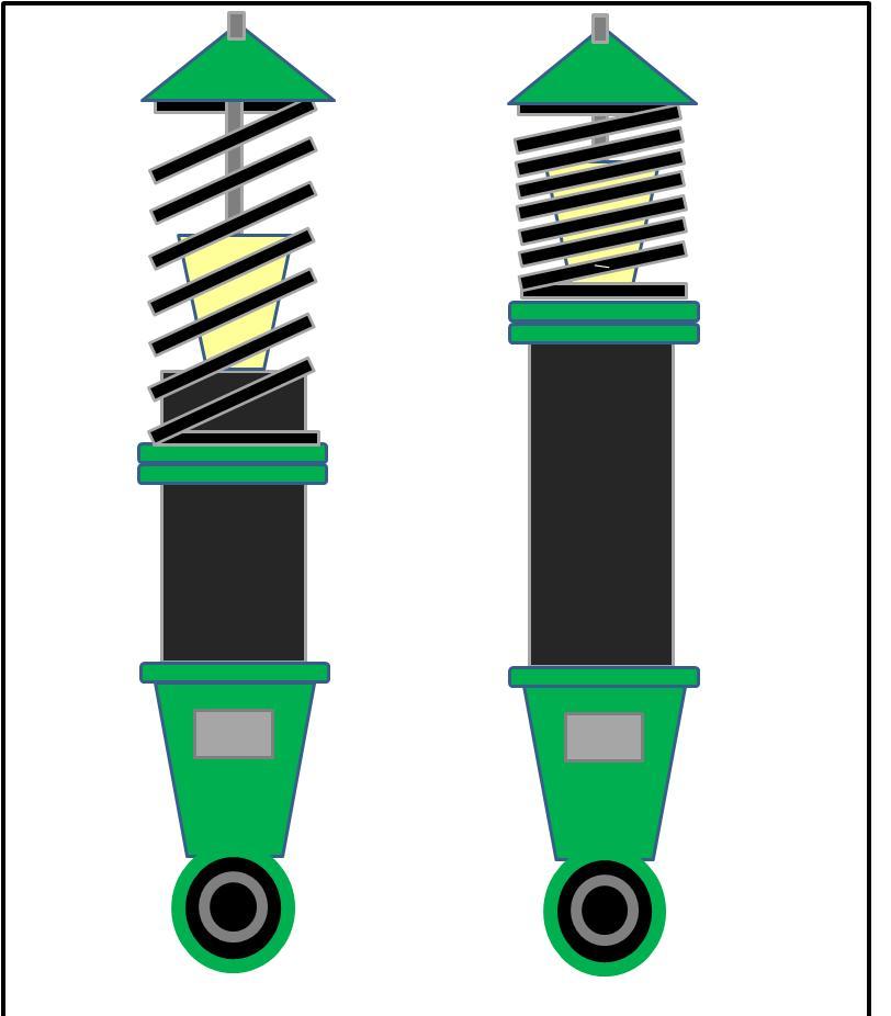
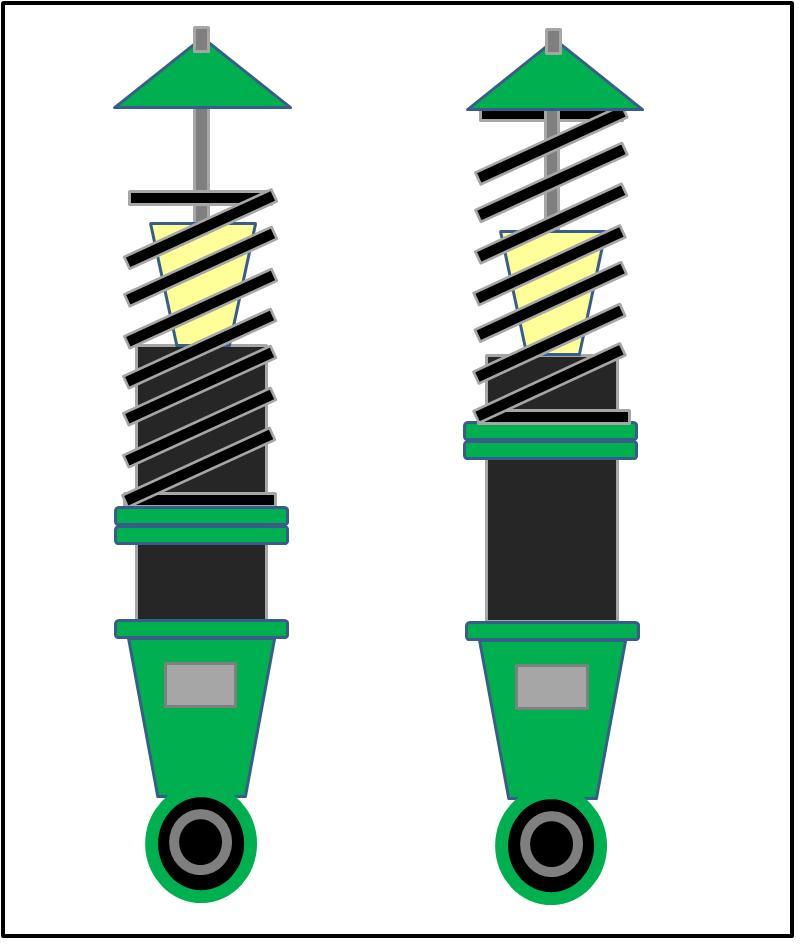
So, adding a catch can into this recirculating system helps by allowing the heavier oil and carbon sludge to fall into the can, while the lighter gases can continue their flow through the intake system. *Yes, that means the catch can must be oriented in a specific way to be able to trap oil/carbon. Basically, tilting the can at an angle, or positioning it sideways will not effectively trap the oil/carbon, especially if there is a lot to be collected.

Do all cars need an oil catch can? Not really. Although every gas powered means of transportation experiences gas blow-by, not all cars have it so badly. However, engines that experience high combustion pressure are more likely to suffer. Turbocharged vehicles also may exhibit more blow-by. So an advanced system to trap the oil and carbon sludge is a good idea, if the car doesn’t already have one. Track cars benefit from catch cans because they constantly see high rpm engine loading, easily increasing the amount of blow-by.

It must also be noted that the reason one end of the recirculating system connects to the intake side is that the vacuum created by the intake cycle helps to pull in the gases more effectively. Make note of that, turbocharged or supercharged car owners. We once had an instance where a customer hooked up one of our Carbing Oil Catch Cans to his supercharged Acura RSX. One end of the system was hooked up properly to the port on the valve cover, while the other end was hooked up to the intake manifold, after the supercharger. That is the incorrect method. You see, if the cylinder head will experience pressure build up, that means pressurized gases are escaping through the valve cover, where a port is already fitted. If you hook the other end up to the the pressurized side of the intake manifold, where boosted air enters, you basically are pressurizing the catch tank from both ends, which does nothing to catch oil and carbon. Although having a supercharger or turbocharger doesn’t mean that highly pressurized air is constantly being fed into the engine (partial throttle, off-throttle coasting), it can be disastrous to the recirculating system if both ends are pressurized.

Again, one end must be pressure fed, while the other is vacuum fed for the system to work properly.

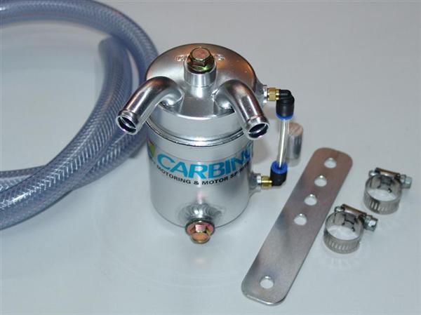
Carbing’s Catch Can is designed to hook up to the factory recirculation system. So, no major modifications are required to install this item, since it replaces one line and links the catch can in between to trap the oil and carbon sludge.

A nice feature of the Carbing Catch Can is that it also has a clear tube gauge to show how full the can is. This comes in handy if you know how often you’re emptying out the can. If you haven’t changed your driving style much, but have to empty the can a bit more frequently, it may mean that you are experiencing some other engine problems. So, it’s a nice safety measure.

Carbing_Oil_Catch_Tank2 (Custom)

For more information on the Carbing Catch Cans, please check out the following link

Carbing.co.jp

TEIN.com

And of course, if you are interested in getting one for your car, but need to find out which size you need, please don’t hesitate to contact us!

Coilover Mixing Headaches

Hey Everyone! Back again with some more tech tips which hopefully help out with you TEIN coilover systems.

Generally around this time of the year we receive many TEIN dampers sent in for our overhaul service. Most customers are looking to do a base repair and possibly consider some replacement parts for the dampers.

P1070270 (Small)

However, some times the parts they are looking for may not exactly be a TEIN part. Some coilover kits we offer at times may not come with the pillowball uppermount as a feature desired and the customer decided to look elsewhere for a mount that they can adapt to the coilover system. Although some companies do claim that their pillow mounts would work with multiple manufacturers, the possiblilty of a misinstallation is still there, as you can see from the attached photos.

P1070284 (Small) P1070281 (Small) P1070279 (Small)


Most pillow mounts offered utilize the following components:

1) A  design-specific lower collar or washer which the bottom of the mount would sit against on the damper piston shaft.

2) A collar or pillow nut (Pillow nuts commonly used on Macpherson strut type dampers) used above the mount to center and maintain the mount bearing to the piston shaft.

3) A top nut (Commonly used on Multi-link type dampers) to secure the mount to the piston shaft.

Even if used on the dampers it may not be the correct type/design for the piston shaft causing the mount to be loose creating noise during normal operation and/or odd wear to the the piston shaft surface which can eventually lead to a break on the shaft, or can even catastrophic internal damages due to a design flaw which would allow the component to bypass the bump stop and max out the damper stroke.

P1070272 (Small) P1070271 (Small) P1070276 (Small)

All of these situations can definitely take a bit out of you wallet and give you a bad headache. With the details and photos shown, I do caution anyone who does consider mix-n-matching coilover system components. Make sure that fitment is solid, and check the fitment if any noises are heard And if multiple collars are required to properly mount, you may want to consider not using the mounts and whether going with another type or just sticking with the coilover manufacturers recommendations. It would save you time, money, and a bad headache.